Check patentability & draft patents in minutes with Patsnap Eureka AI!

Visual detection device and method for surface scratches of plane thrust bearing retainer

A technology of visual detection device and thrust bearing, which is applied in the direction of measuring device, optical device, optical test for defects/defects, etc., can solve the problems of inability to meet the requirements of product quality inspection, low efficiency, high cost, etc., and achieve improved detection efficiency and The effect of sorting speed, improving detection efficiency and reducing labor cost

Pending Publication Date: 2020-09-22
CHINA JILIANG UNIV
View PDF0 Cites 1 Cited by
  • Summary
  • Abstract
  • Description
  • Claims
  • Application Information

AI Technical Summary

Problems solved by technology

This method of detection is not only costly and inefficient, but also labor-intensive. After long-term work, visual fatigue is prone to errors, and the reliability of the test results is poor. It can no longer meet the requirements of buyers for product quality inspection and the transformation and development of enterprises themselves. need

Method used


Image

  • Visual detection device and method for surface scratches of plane thrust bearing retainer
  • Visual detection device and method for surface scratches of plane thrust bearing retainer
  • Visual detection device and method for surface scratches of plane thrust bearing retainer

Examples


Embodiment Construction

[0024] The present invention will be further described below in conjunction with the accompanying drawings and specific implementation methods (embodiments), but it is not used as a basis for limiting the present invention.

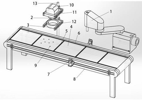
[0025] Such as figure 1 As shown, the present invention consists of a mechanical arm sorting device 1, an industrial CCD camera 2, a ring light source 3, a conveyor belt mechanism 4, a transparent partition bar 5, an opaque baffle 6, a position detection mechanism 7, a frame 8, a camera fixing plate 10, Camera support frame 11, light source support frame 12, slide bar 13 are formed.

[0026] The conveyor belt mechanism 4 is fixed on the frame 8, and the opaque baffles 6 are adhered to both sides of the conveyor belt. The plurality of transparent partition bars 5 are equally spaced across and fixed on the conveyor belt mechanism 4. Several opaque baffles The plate 6 is installed between two transparent partition bars to form a rectangular basket with the ...


PUM


Abstract

The invention discloses an online detection device for surface scratches of a plane thrust bearing frame based on machine vision. The device comprises a mechanical arm sorting device, an industrial CCD camera, an annular light source, a conveying belt mechanism, transparent separation strips, opaque baffles, a position detection mechanism, a rack, a camera fixing plate, a camera supporting frame,a light source supporting frame and a sliding rod. The opaque baffles are adhered to the two sides of the conveying belt mechanism, the transparent separation strips are fixed to the conveying belt mechanism in an equally-spaced crossing mode, and the sliding rod is fixed to one side of the rack. The camera supporting frame is fixed to the sliding rod, the camera fixing plate is installed on the camera supporting frame, and the industrial CCD camera is fixed to the camera fixing plate. The light source supporting frame is fixed to the sliding rod, the annular light source is fixed to the lightsource supporting frame, the industrial CCD camera is located over the annular light source, and the mechanical arm sorting device is located at one side of the rack. According to the invention, surface scratches of a plurality of plane thrust bearing retainers on a conveying belt can be detected at the same time, unqualified parts can be sorted, and the detection efficiency is high.

Description

technical field [0001] The invention relates to a device for detecting scratches on the surface of a plane thrust bearing cage, in particular to a device and method for automatically detecting scratches on the surface of a plane thrust bearing cage by using machine vision technology. Background technique [0002] Plane thrust bearing cage is a basic part of automobile plane thrust bearing, and its surface defects will affect the working condition and service life of the bearing, which in turn will affect the quality and safety performance of the vehicle. At present, the detection of scratches on the surface of the cage by various manufacturers is completely carried out by manual observation with the naked eye. This method of detection is not only costly and inefficient, but also labor-intensive. After long-term work, visual fatigue is prone to errors, and the reliability of the test results is poor. It can no longer meet the requirements of buyers for product quality inspect...

Claims


Application Information

Patent Timeline
IPC IPC(8): G01N21/88G01N21/01G01N21/13G01B11/00B07C5/02B07C5/342B07C5/36
CPCB07C5/02B07C5/3422B07C5/362B07C2501/0063G01B11/002G01N21/01G01N21/13G01N21/88G01N21/8851G01N2021/8887G01N2201/0438G01N2201/0461
Inventor 陈晨煜杨雷陈爱军庞煜剑石赛凡王睿骁
Owner CHINA JILIANG UNIV
Features
  • R&D
  • Intellectual Property
  • Life Sciences
  • Materials
  • Tech Scout
  • Unparalleled Data Quality
  • Higher Quality Content
  • 60% Fewer Hallucinations
Learn More