
Camera device

A camera device and image processing technology, applied in image communication, TV, color TV components and other directions, can solve problems affecting image or video transmission, etc., achieve data exchange, realize wired connection, fast and stable transmission. Effect

Pending Publication Date: 2020-09-22
SHENZHEN YONG NUO PHOTOGRAPHIC EQUIP CO LTD
View PDF0 Cites 1 Cited by
  • Summary
  • Abstract
  • Description
  • Claims
  • Application Information

AI Technical Summary

Problems solved by technology

[0003] The purpose of the embodiments of the present application is to provide a camera device to solve the problem in the related art that the connection between the camera and the electronic device is restricted by region through a wireless network, thus affecting the transmission of images or videos between the camera and the electronic device

Method used


Image

  • Camera device
  • Camera device
  • Camera device

Examples


Embodiment 1

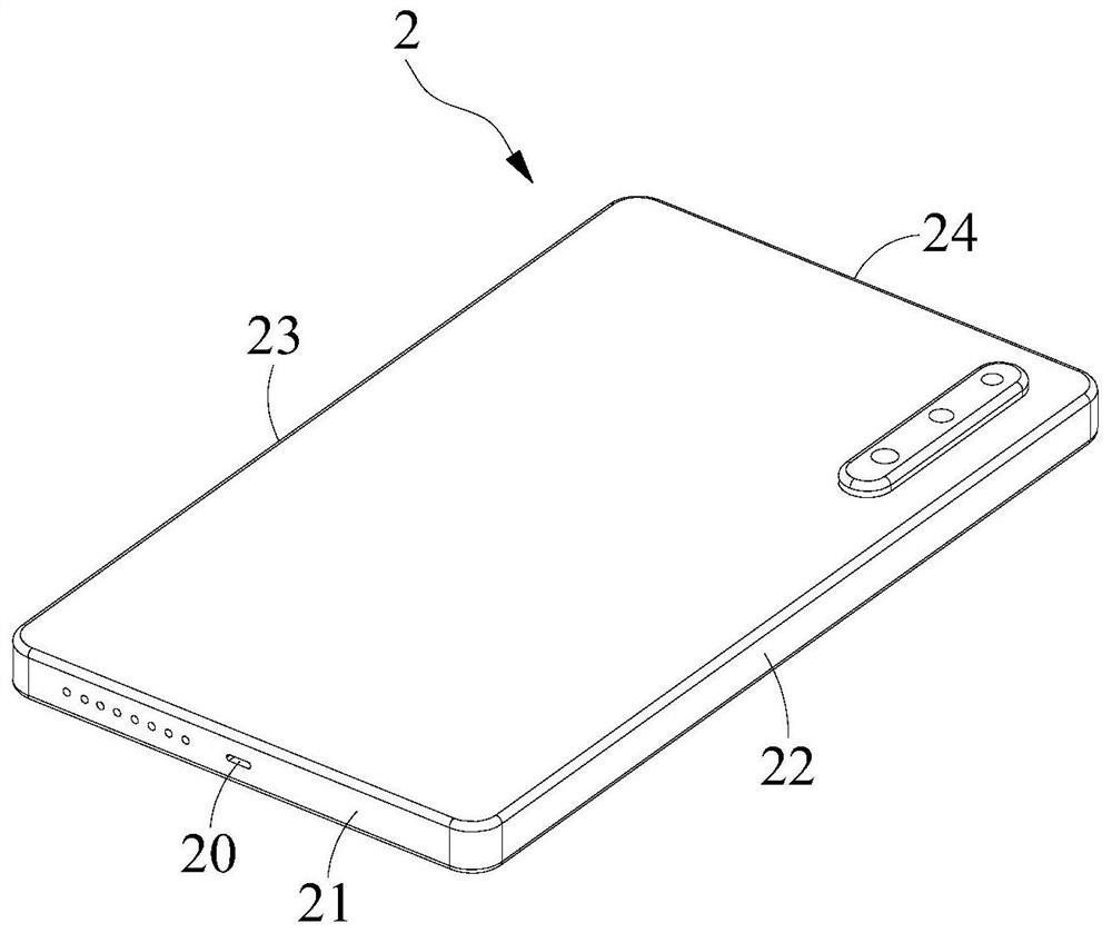
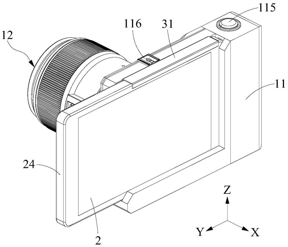
[0043] see figure 1 , figure 2 and Figure 5 , the imaging device provided in Embodiment 1 of the present application will now be described. The imaging device includes a camera body 1; the camera body 1 includes a casing 11, a lens 12 connected to the casing 11, and a main control unit 13, a power supply unit 14, a wireless network unit 15, and an image respectively installed in the casing 11. The processing unit 16 and the photosensitive unit 17 ; the power supply unit 14 , the wireless network unit 15 and the image processing unit 16 are respectively electrically connected to the main control unit 13 , and the photosensitive unit 17 is electrically connected to the image processing unit 16 . The camera device also includes a plug 4 for electrical connection with the interface 20 of the external electronic device 2 ; the plug 4 is installed on the casing 11 , and the plug 4 is electrically connected with the main control unit 13 . Wherein, the electronic device 2 may be ...

Embodiment 2

[0057] see Figure 10 to Figure 12 , the camera device provided in Embodiment 2 of the present application will now be described. The difference between the imaging device provided in Embodiment 2 of the present application and the imaging device provided in Embodiment 1 above is that the clamping plate includes a second clamping plate 32 installed on the casing 11 and is used to elastically pull the second clamping plate 32 along the casing 11. The length direction moves to cooperate with the first card slot 112 to clamp the second elastic member (not shown) of the electronic device 2; one end of the second elastic member is connected with the casing 11, and the other end of the second elastic member is connected with the second The splints 32 are connected. Wherein, the second elastic member can be a spring. With this structure, when the electronic device 2 is installed, the second splint 32 is pulled outward along the Y-axis direction, and the second elastic member is in ...


PUM


Abstract

The invention provides a camera device. The camera device comprises a camera body; the camera body comprises a shell, a lens connected with the shell, and a main control unit, a power supply unit, a wireless network unit, an image processing unit and a photosensitive unit which are respectively arranged in the shell; and the device further comprises a plug which is used for being electrically connected with an interface of external electronic equipment. According to the application, the plug electrically connected with the main control unit is installed on the shell, and the plug can be connected with the interface of the electronic equipment, so that wired connection between the electronic equipment and the camera body is realized. In an area without the wireless network, the electronicequipment can be connected with the camera body through the plug, so that data exchange between the camera body and the electronic equipment is realized, and transmission of images or videos is realized. Therefore, wireless connection and wired connection can be realized between the camera body and the electronic equipment, the connection modes are various and are not limited by regions, and images or videos can be quickly and stably transmitted between the camera body and the electronic equipment.

Description

technical field [0001] The present application belongs to the technical field of cameras, and more specifically relates to an imaging device. Background technique [0002] In order to obtain better picture quality, people prefer to use professional cameras to take pictures or videos instead of electronic devices such as mobile phones and tablet computers. The current camera mainly includes a casing, a power supply unit installed in the casing, a lens installed on the casing, a photosensitive unit for cooperating with the lens to obtain image information, an image processing unit for processing the acquired image, and The main control unit used to control the lens, photosensitive unit and image processing unit respectively. In order to send the images or videos captured by the camera to electronic equipment, some cameras are also equipped with a wireless network unit electrically connected to the main control unit, through which the wireless data transmission terminal can re...

Claims


Application Information

Patent Timeline
Patent Type & Authority Applications(China)
IPC IPC(8): H04N5/225H04N5/232
CPCH04N23/53H04N23/51H04N23/50H04N23/57H04N23/66H04N23/663H04N23/65
Inventor 徐健伟庄永盛庄建南
Owner SHENZHEN YONG NUO PHOTOGRAPHIC EQUIP CO LTD
Learn More