
Push-leaning type rotary guiding device

A technology of rotary steering and conductive slip ring, which is applied in the direction of rotary collector, directional drilling, measurement, etc., can solve the problems of unable to correct the drilling trajectory in time, increase the area of ​​the piston, and increase the size of the hydraulic system. Effects of power supply and communication, improvement of ramping ability, and reduction of design difficulty

Pending Publication Date: 2022-06-24
CHINA OILFIELD SERVICES
View PDF0 Cites 0 Cited by
  • Summary
  • Abstract
  • Description
  • Claims
  • Application Information

AI Technical Summary

Problems solved by technology

[0003] In the prior art, the push-to-type rotary steerable tool usually has the following defects in specific use: 1) The push-to-type rotary steerable tool in the prior art usually only has the function of measuring the inclination near the drill bit, and with the With the development of oil exploration and development technology, more measurement functions need to be integrated. Due to the complex structure of the push-to-type rotary steerable tool, other measurement functions are often integrated into the rotary steerable instrument in the prior art, thereby increasing the measurement distance.
For geosteering, increasing the measurement distance often occurs after the drill bit has drilled out of the reservoir for a certain distance, and the measurement module can find this situation, so that the drilling trajectory cannot be corrected in time; 2) the deflection of the existing rotary steering tool The capacity mainly depends on the hydraulic pushing module. If you want to improve the tilting ability of the rotary steerable tool, you need to increase the pushing force of the hydraulic pushing module.
This requires increasing the hydraulic pressure or increasing the piston area, which increases the size of the hydraulic system, which is not conducive to the design and application of rotary steerable tools

Method used


Image

  • Push-leaning type rotary guiding device
  • Push-leaning type rotary guiding device
  • Push-leaning type rotary guiding device

Examples


Embodiment Construction

[0024] In order to better understand the purpose, structure and function of the present invention, a push-type rotary guide device of the present invention will be described in further detail below with reference to the accompanying drawings.

[0025] figure 1 It is a schematic structural diagram of some embodiments of the push-type rotary guide device according to the embodiment of the present invention;

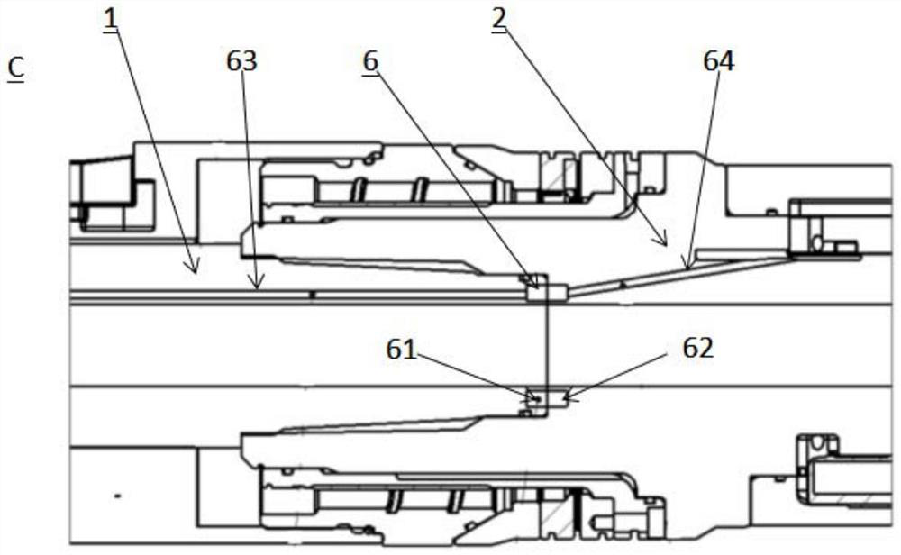
[0026] figure 2 It is a schematic cross-sectional view of the structure of some embodiments of the push-type rotary guide device according to the embodiment of the present invention. combine figure 1 , figure 2 as well as Figure 5 As shown, the push-type rotary guide device 100 includes: an upper driving shaft 1 and a lower driving shaft 2, the upper driving shaft 1 and the lower driving shaft 2 are coaxially arranged and fixedly connected, and the upper driving shaft 1 is used for connecting with an external driving device , the end of the lower drive shaft 2 is pr...


PUM


Abstract

The invention relates to a pushing type rotary guiding device which comprises an upper driving shaft and a lower driving shaft, the upper driving shaft and the lower driving shaft are coaxially arranged and fixedly connected, and a circuit control module and a hydraulic pushing module are sequentially arranged on the peripheral wall of the upper driving shaft; a gamma measurement module is arranged on the peripheral wall of the lower driving shaft, and a measurement control circuit and an orientation measurement module electrically connected with the measurement control circuit are arranged in the gamma measurement module; and the electric connection system comprises an electric connection part, a communication module and a cable, the electric connection part is arranged on the connection end part of the upper driving shaft and the lower driving shaft, and the communication module is arranged in the circuit control module and the hydraulic pushing module. The measurement control circuit is connected with the electric connection component through a cable, the electric connection component is connected with the circuit control module through a cable, and the circuit control module is connected with the hydraulic pushing module through the communication module. According to the pushing type rotary guiding device, the distance between a gamma measuring point and a drill bit can be shortened, and the deflecting capacity of the pushing type rotary guiding device is improved.

Description

technical field [0001] The invention belongs to the technical field of petroleum exploration and development, and particularly relates to a push-type rotary guide device. Background technique [0002] The existing push-type rotary guide tool is mainly composed of an upper drive shaft, a circuit control module, a hydraulic push-up module, a lower drive shaft and other components. The upper drive shaft is connected to the drive device, the lower drive shaft is provided with a drill bit, and the circuit control module receives commands to control the magnitude and direction of the resultant force provided by the hydraulic pushing module, so that the rotary steering tool can perform directional drilling as required. [0003] In the prior art, the push-type rotary steerable tools usually have the following defects in specific use: 1) The push-push rotary steerable tools in the prior art usually only have the function of measuring the inclination near the drill bit, and with the ...

Claims


Application Information

Patent Timeline
Patent Type & Authority Applications(China)
IPC IPC(8): E21B7/06E21B47/12E21B17/10H01R39/08
CPCE21B7/06E21B47/12E21B17/10E21B7/061H01R39/08
Inventor 贾建波兰洪波尚捷孙师贤菅志军张玉霖张冠祺孟巍朱伟红丁旭东吉玲王红亮李辉药晓江
Owner CHINA OILFIELD SERVICES
Learn More