
A waist massage device

A waist and massage technology, applied in the field of medical equipment, can solve the problems of low intelligence, single treatment method, limited treatment effect, etc., and achieve good results

Active Publication Date: 2022-04-01
UNIV OF SHANGHAI FOR SCI & TECH
View PDF6 Cites 0 Cited by
  • Summary
  • Abstract
  • Description
  • Claims
  • Application Information

AI Technical Summary

Problems solved by technology

Comparing the traction beds at home and abroad, it is found that there are the following shortcomings or deficiencies: firstly, the existing products are relatively low in intelligence, and many traction beds are still in the mode of mechanical manual control
Secondly, most traction beds mainly complete the rehabilitation training program through traction and stretching between the upper and lower limbs. The treatment method is relatively simple and the treatment effect is limited.

Method used


Image

  • A waist massage device
  • A waist massage device
  • A waist massage device

Examples


Embodiment 1

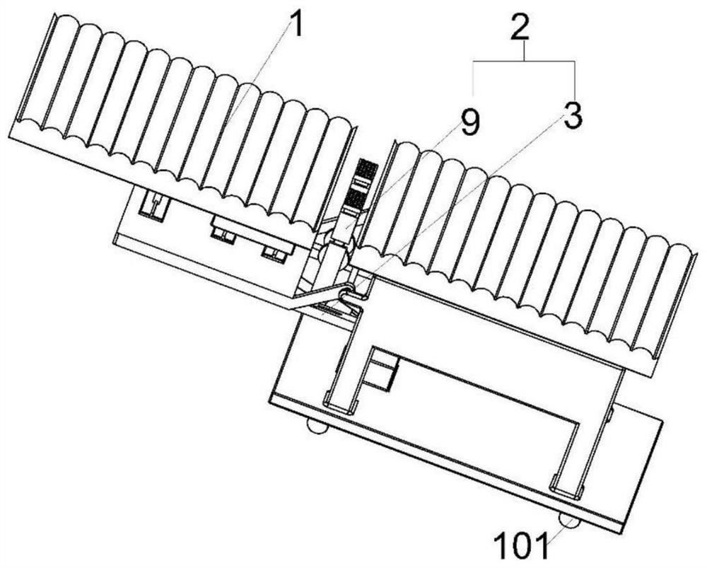
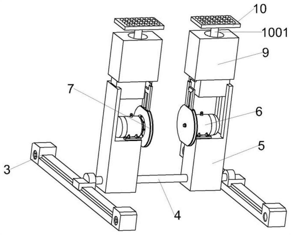
[0030] A waist massage device, comprising a massage unit 2; the massage unit 2 includes two linear motors 3, a support frame 4 vertically fixed between the two linear motors 3, a support arm 5 slidably connected to the support frame 4 top and arranged on The servo motor 6 in the middle of the support arm 5 and the vibration assembly connected to the servo motor 6; the massage part is slidingly arranged on the top of the vibration assembly, the servo motor 6 is used to drive the vibration assembly, and the vibration assembly is used to vibrate the massage part. The massage device is fixed on the gap in the middle of the traction bed 3 by the linear motor 3, and the position of the massage part can be adjusted through the sliding fit of the support frame 4 and the support arm 5 so as to find a position that is more suitable for massage between the horizontal positions of the waist.

[0031] In a further optimization scheme, the vibration assembly includes a housing 7 fixedly conn...

Embodiment 2

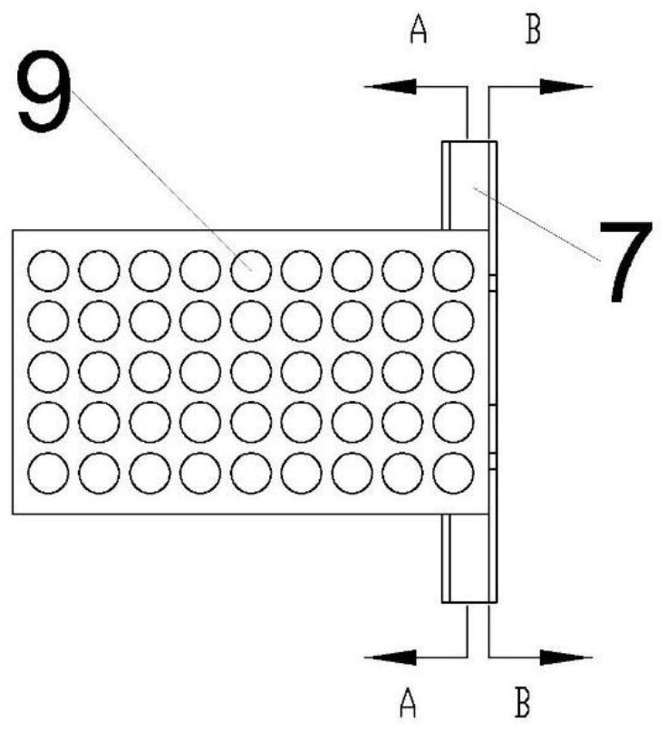
[0043] The difference between the massage device of this embodiment and the first embodiment is that the lifting arm 9 is a hollow structure, the lifting arm 9 is provided with a lifting adjustment cylinder 1001, and the output shaft of the lifting adjustment cylinder 1001 is fixed with a lifting adjustment block 10. , The top surface of the lifting adjustment block 10 is provided with a protrusion. The pressure sensor transmits the pressure signal to the PLC controller, and the PLC controller adjusts the lifting adjustment cylinder 1001 to adjust the height of the lifting block 10 to realize the adjustment of the massage force.

Embodiment 3

[0045] The difference between the massage device of this embodiment and the second embodiment is that an inflation valve is provided on the side wall of the housing 7 corresponding to the first cavity 11, and an air inlet valve is provided on the side wall of the housing 7 corresponding to the second cavity 12. One-way valve, the side wall of the housing 7 corresponding to the third cavity 13 is provided with an air outlet one-way valve. By adding an inflation valve, the pressure of the gas in the first cavity 11 can be adjusted, so as to achieve the purpose of adjusting the massage intensity. The position of the air inside and the outside air is balanced, reducing the torque consumption during the rotation process of the rotor 702 driven by the servo motor 6, thereby improving the efficiency of the device.


PUM


Abstract

The invention relates to the field of medical equipment, in particular to a waist massage device. It includes a traction bed with a gap in the middle and a massage unit arranged in the gap of the traction bed; the massage unit includes two linear motors fixedly connected with the traction bed, vertically and slidingly arranged on the two linear motors The supporting frame, the supporting arm slidably connected on the upper part of the supporting frame and the vibration assembly arranged on the upper part of the supporting arm; the upper part of the vibration assembly is slidingly fitted with a massage part. The invention provides a waist massage device applied to a traction bed, which can adjust massage parts.

Description

technical field [0001] The invention relates to the field of medical equipment, in particular to a waist massage device. Background technique [0002] Lumbar intervertebral disc herniation, cervical spondylosis, thoracolumbar posterior joint disorder, and spine-related diseases and other soft tissue injury diseases between the spine and vertebrae (abbreviated as intervertebral diseases) are some common persistent diseases. Relevant surveys show that 97% of middle-aged and elderly people in my country suffer from spinal diseases. The sickness rate of scoliosis is as high as more than 25%. With the continuous development of our society, office white-collar workers, students and teachers have long-term lack of effective exercise and sedentary activities, and long-term accumulation will cause spinal injuries. In addition, waist injuries will also affect the lives of motor vehicle drivers for a long time. The application population of the lumbar traction system has expanded from...

Claims


Application Information

Patent Timeline
Patent Type & Authority Patents(China)
IPC IPC(8): A61H23/02A61H1/02
CPCA61H23/02A61H1/0218A61H2201/1207A61H2201/1246A61H2205/08
Inventor 杜妍辰张鑫周琦江伟张依雯张诗仪
Owner UNIV OF SHANGHAI FOR SCI & TECH
Learn More