
Processing clamp for lug hole of landing gear buffer outer cylinder

A landing gear buffer and lug hole technology, which is applied in the direction of manufacturing tools, metal processing equipment, metal processing machinery parts, etc., can solve the problems of difficulty in processing lug holes and limited processing tools, and achieve simple structure and low processing cost. Low, easy to find the effect of parts

Active Publication Date: 2020-09-25
LANDING GEAR ADVANCED MFG
View PDF8 Cites 0 Cited by
  • Summary
  • Abstract
  • Description
  • Claims
  • Application Information

AI Technical Summary

Problems solved by technology

For some special-shaped models where the axis of the lug hole of the outer cylinder of the landing gear buffer is not parallel to the axis of the outer cylinder of the landing gear buffer itself, it will become very difficult to process the lug hole
The conventional machining plan is to process on a five-axis machining center, but limited by the purchase of machining tools, it is necessary to adjust the parts to be processed on a horizontal machining center. This requires designing a set of fixtures to place the parts obliquely to ensure that the parts to be processed Hole axis parallel to tool axis for machining on horizontal machining centers

Method used


Image

  • Processing clamp for lug hole of landing gear buffer outer cylinder
  • Processing clamp for lug hole of landing gear buffer outer cylinder
  • Processing clamp for lug hole of landing gear buffer outer cylinder

Examples


Embodiment Construction

[0040] In order to make the objectives, technical solutions, and advantages of the embodiments of the present invention clearer, the technical solutions of the embodiments of the present invention will be described clearly and completely in conjunction with the accompanying drawings of the embodiments. Obviously, the described embodiments are part of the embodiments of the present invention, rather than all of the embodiments. Based on the described embodiments of the present invention, all other embodiments obtained by those of ordinary skill in the art without creative labor are within the protection scope of the present invention. The "first", "second" and similar words used in the present invention do not indicate any order, quantity or importance, but are only used to distinguish different components. It should be noted that the embodiments of the present invention and the features in the embodiments can be combined with each other if there is no conflict.

[0041] At least...


PUM


Abstract

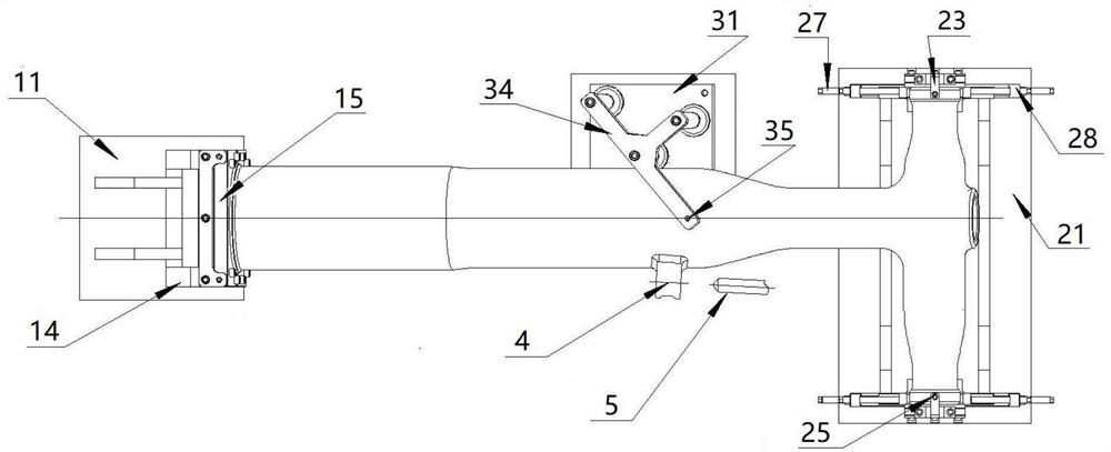
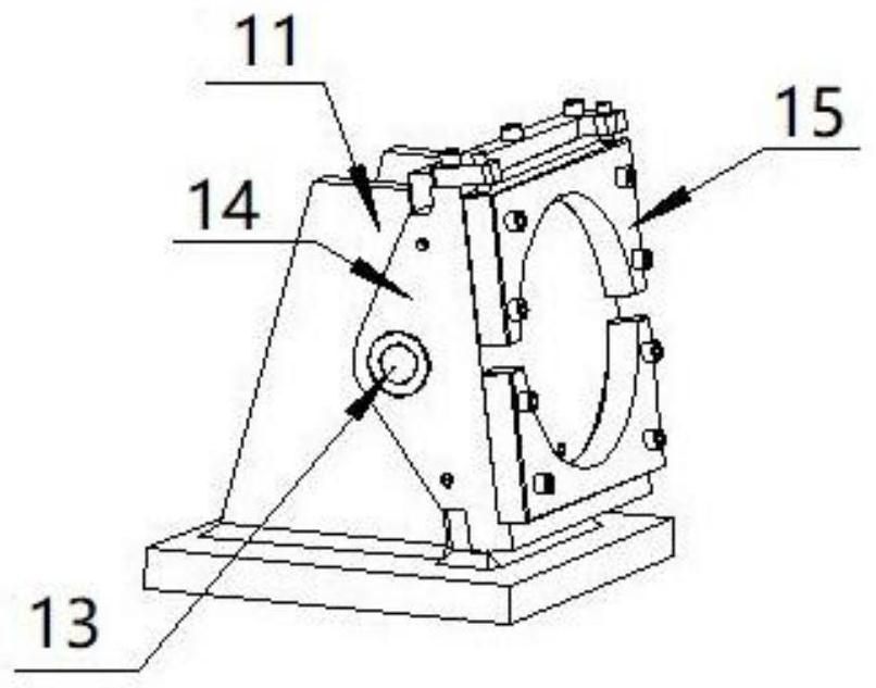
The invention provides a processing clamp for a lug hole of a landing gear buffer outer cylinder. The processing clamp comprises a rotating support device and a fixed support device, wherein the rotating support device comprises a first support, a rotating baffle and an outer fixed plate; the rotating baffle is composed of a base plate and two side plates respectively located at the two sides of the base plate; the two side plates of the rotating baffle are hinged to the first support, the base plate of the rotating baffle is detachably connected with an outer circle fixed plate, a circular hole is formed in the outer circle fixed plate, and a locking structure is also arranged at the connection between the rotating baffle and the first support; the fixed support device comprises a secondsupport and limiting assemblies; two groups of limiting assemblies are provided and correspondingly arranged at the two ends of the second support; and each group of limiting assembly comprises an upper limiting block and a lower limiting block, the upper limiting block is positioned above the lower limiting block, and the lower limiting block is connected with a height adjusting assembly.

Description

Technical field [0001] The invention belongs to the technical field of tooling, and particularly relates to a fixture for processing lug holes of the outer cylinder of a landing gear buffer. Background technique [0002] The outer cylinder parts of the strut type landing gear buffer are usually designed with lugs and lug holes that connect the struts. The size of the ear piece is small, the distance between the center of the ear piece hole and the outer circular surface of the outer cylinder is small, and the diameter and position tolerance of the ear piece hole need to be strictly controlled. For some special-shaped models in which the axis of the lug hole of the outer cylinder of the landing gear buffer is not parallel to the axis of the outer cylinder of the landing gear buffer itself, it becomes very difficult to process the lug hole. The conventional processing plan is to process on a five-axis machining center, but limited to the purchase of processing tools, the parts nee...

Claims


Application Information

Patent Timeline
IPC IPC(8): B23Q3/06
CPCB23Q3/062
Inventor 贺欣兴张帆吴红军孟辉付隔清夏新远杨连群陈伟龙
Owner LANDING GEAR ADVANCED MFG
Learn More