An automatic noodle cutting device
An automatic cutting device and noodle technology, which is applied in metal processing and other directions, can solve the problems of reduced work efficiency, easy soreness, labor and so on, and achieve the effect of high work efficiency
- Summary
- Abstract
- Description
- Claims
- Application Information
AI Technical Summary
Problems solved by technology
Method used
Image
Examples
Embodiment 1
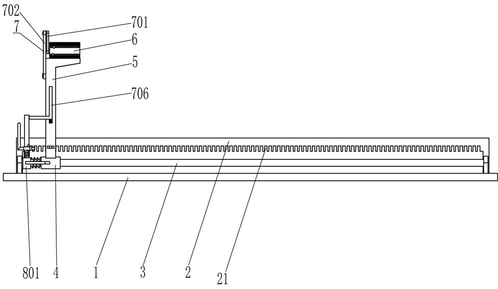
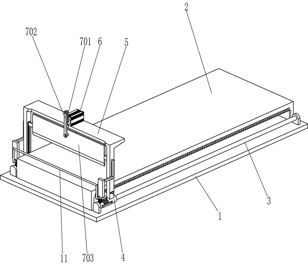
[0021] An automatic noodle cutting device, such as Figure 1-3 As shown, it includes a base plate 1, a placing plate 2, a guide rod 3, a first sliding sleeve 4, an n-type plate 5, a servo motor 6, a cutting assembly 7 and a moving assembly 8, and a placing plate 2 is fixed in the middle of the top of the base plate 1. There are grooves 21 evenly spaced on the top, front and back sides of the placing plate 2. Guide rods 3 are fixedly connected to the middle of the top, front and rear sides of the bottom plate 1. The guide rods 3 are located on the front and rear sides of the placing plate 2. The first sliding sleeve 4 is provided with a first sliding sleeve 4, and there are grooves on the left side of the front and rear sides of the first sliding sleeve 4, and an n-type plate 5 is fixed between the outer top of the first sliding sleeve 4 on the front and rear sides. A servo motor 6 is installed in the middle of the top by bolting, a cutting assembly 7 is arranged between the en...
Embodiment 2
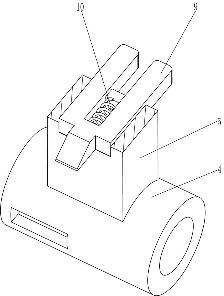
[0028] On the basis of Example 1, as image 3 and Figure 4 As shown, it also includes a clamping block 9 and a fourth spring 10. The lower parts of the front and rear sides of the n-type plate 5 are slidably connected with the clamping block 9. The clamping block 9 is located under the slider 704, and the clamping block 9 is connected to the contact frame 706. Matching, the clamping block 9 also cooperates with the groove 21, the inner front side of the front side clamping block 9 is connected with the fourth spring 10 before the inner side of the front side of the n-type plate 5, and the inner and rear sides of the rear side clamping block 9 are connected to the back of the n-type plate 5. A fourth spring 10 is also connected between the side interiors.
[0029] When the contact frame 706 moves downward, the contact frame 706 contacts the contact rod 807, the third spring 808 is compressed, the third sliding sleeve 805 drives the clamping rod 806 to move downward, the clamp...
PUM
 Abstract
Description
Claims
Application Information
 - R&D
- Intellectual Property
- Life Sciences
- Materials
- Tech Scout
- Unparalleled Data Quality
- Higher Quality Content
- 60% Fewer Hallucinations
Browse by: Latest US Patents, China's latest patents, Technical Efficacy Thesaurus, Application Domain, Technology Topic, Popular Technical Reports.
© 2025 PatSnap. All rights reserved.Legal|Privacy policy|Modern Slavery Act Transparency Statement|Sitemap|About US| Contact US: help@patsnap.com


