Additive manufacturing device and additive manufacturing method

A technology for additive manufacturing, powder box

Inactive Publication Date: 2020-09-25
QUICKBEAM CO LTD
View PDF10 Cites 5 Cited by
  • Summary
  • Abstract
  • Description
  • Claims
  • Application Information

AI Technical Summary

Problems solved by technology

[0004] The purpose of the present invention is to provide an additive manufacturing device and an ad

Method used


Image

  • Additive manufacturing device and additive manufacturing method
  • Additive manufacturing device and additive manufacturing method
  • Additive manufacturing device and additive manufacturing method

Examples


Embodiment 1

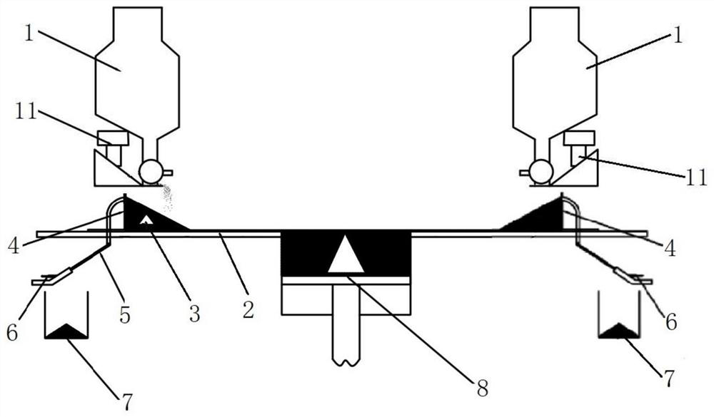
[0034] This embodiment provides an additive device, such as figure 1 As shown, the additive device includes a powder box 1, a powder spreading platform 2, a scraper 3, a powder baffle plate 4, a powder falling channel 5, a sensor 6, and a forming cylinder 8. The powder box 1, the powder spreading platform 2, and the scraper 3 , powder baffle plate 4, powder falling channel 5, sensor 6 and forming cylinder 8 are all placed in the forming chamber of vacuum to realize additive manufacturing. In this embodiment, the remaining powder is accumulated by setting the powder baffle plate 4, which can make the powder slope-shaped, and the powder falling channel 5 is set. When the remaining powder is piled up enough, the powder will enter the powder falling channel 5 and then pass through the sensor. 6. Detect the powder falling information of the falling powder (such as powder falling amount or powder falling time), and the amount of accumulated powder can be known according to the powde...

Embodiment 2

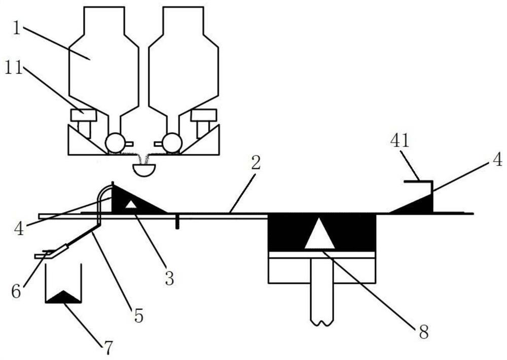
[0050] This embodiment provides an additive manufacturing device, which is different from Embodiment 1 in that the location of the powder falling channel 5 in this embodiment is different. Specifically, such as Figure 4 As shown, the powder falling channel 5 of this embodiment is set on the powder spreading platform 2 , and is specifically set on the side of the powder baffle plate 4 close to the forming cylinder 8 . There is a second through hole on the powder spreading platform 2, and the powder falling channel 5 is connected to the second through hole and placed under the powder spreading platform 2. When the remaining powder accumulates a lot, part of the remaining powder can fall through the second through hole. It enters the powder falling channel 5 and is detected by the sensor 6.

[0051] It can be understood that the powder box 1 of this embodiment can also be set to one or two according to needs, and when there are two powder boxes 1, the two powder boxes 1 can be ...


PUM


Abstract

The invention belongs to the technical field of additive manufacturing, and discloses an additive manufacturing device and an additive manufacturing method. The additive manufacturing device comprisespowder boxes, a powder laying platform arranged below the powder boxes, scrapers arranged on the powder laying platform, powder stopping plates arranged at the two sides of the powder laying platform, powder falling channels arranged at at least one powder stopping plate and sensors arranged at the powder falling channels. The powder stopping plates are configured to stack residual powder obtained after the scrapers conduct powder spreading; and the powder falling channels are configured to detect powder falling information of powder fallen into the powder falling channels to control the amount of powder conveyed when the powder boxes conduct powder feeding next time. According to the additive manufacturing device and the additive manufacturing method, the amount of powder conveyed next time by the powder boxes can be controlled to achieve the purpose of repeatedly utilizing the residual powder, the powder utilization rate is increased, and the powder in the powder boxes can be supplied for a long term for printing.

Description

technical field [0001] The invention relates to the technical field of additive manufacturing, in particular to an additive manufacturing device and an additive manufacturing method. Background technique [0002] In the process of additive manufacturing, usually the amount of powder conveyed by each layer is greater than the amount of powder required by each layer, and the remaining powder will overflow into the powder collection box or accumulate on both sides of the powder collection position after each powder feeding. Instead of participating in the powder feeding of the next layer, the remaining powder will always accumulate or overflow, which will affect the amount of powder required for long-term printing. [0003] In the existing technology, when the powder height reaches the powder outlet, the powder supply is stopped, and the powder is spread and fed after the scraper takes the powder. However, when the scraper takes the powder, the powder will be pushed to the back...

Claims


Application Information

Patent Timeline
IPC IPC(8): B29C64/141B29C64/214B29C64/321B29C64/386B29C64/393B33Y10/00B33Y30/00B33Y50/00B33Y50/02B33Y40/00
CPCB33Y10/00B33Y30/00B33Y40/00B33Y50/00B33Y50/02B29C64/141B29C64/214B29C64/321B29C64/386B29C64/393
Inventor 郭超鲁金鑫孙永鑫李龙马旭龙阚文斌
Owner QUICKBEAM CO LTD
Why Eureka
Try Eureka