A waste wire packaging device for construction waste recycling

A technology for construction waste and wire, which is applied in packaging, bundling materials, components of bundling machinery, etc.

Active Publication Date: 2022-01-07
环创(赤峰)科技有限公司
View PDF6 Cites 0 Cited by
  • Summary
  • Abstract
  • Description
  • Claims
  • Application Information

AI Technical Summary

Problems solved by technology

[0006] In order to overcome the problem of manually smoothing the loose waste thread by hand, the present invention quickly puts the waste thread of construction into the rotating shaft for tape winding. In the process of tape winding, manual hands hold the waste thread for winding, which is safe. Hidden dangers, and this kind of complicated operation will increase the shortcoming of the workload of the packing belt. The technical problem to be solved by the present invention is to provide a foot-operated foot-operated belt for the field of batch packing that can not only exercise the body, but also push the construction waste line firmly. waste line packaging device

Method used


Image

  • A waste wire packaging device for construction waste recycling
  • A waste wire packaging device for construction waste recycling
  • A waste wire packaging device for construction waste recycling

Examples


Embodiment 1

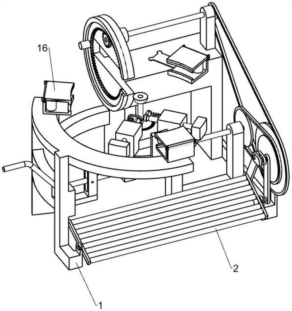
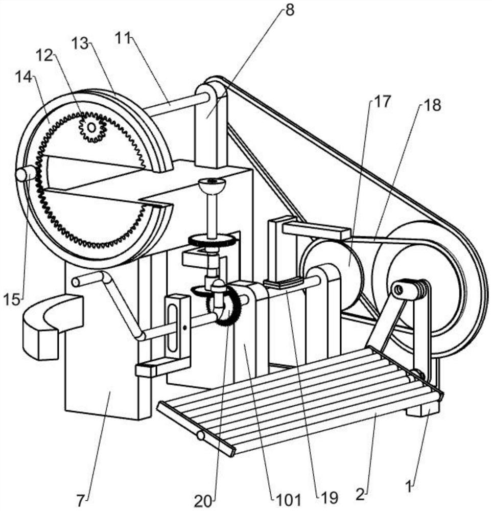
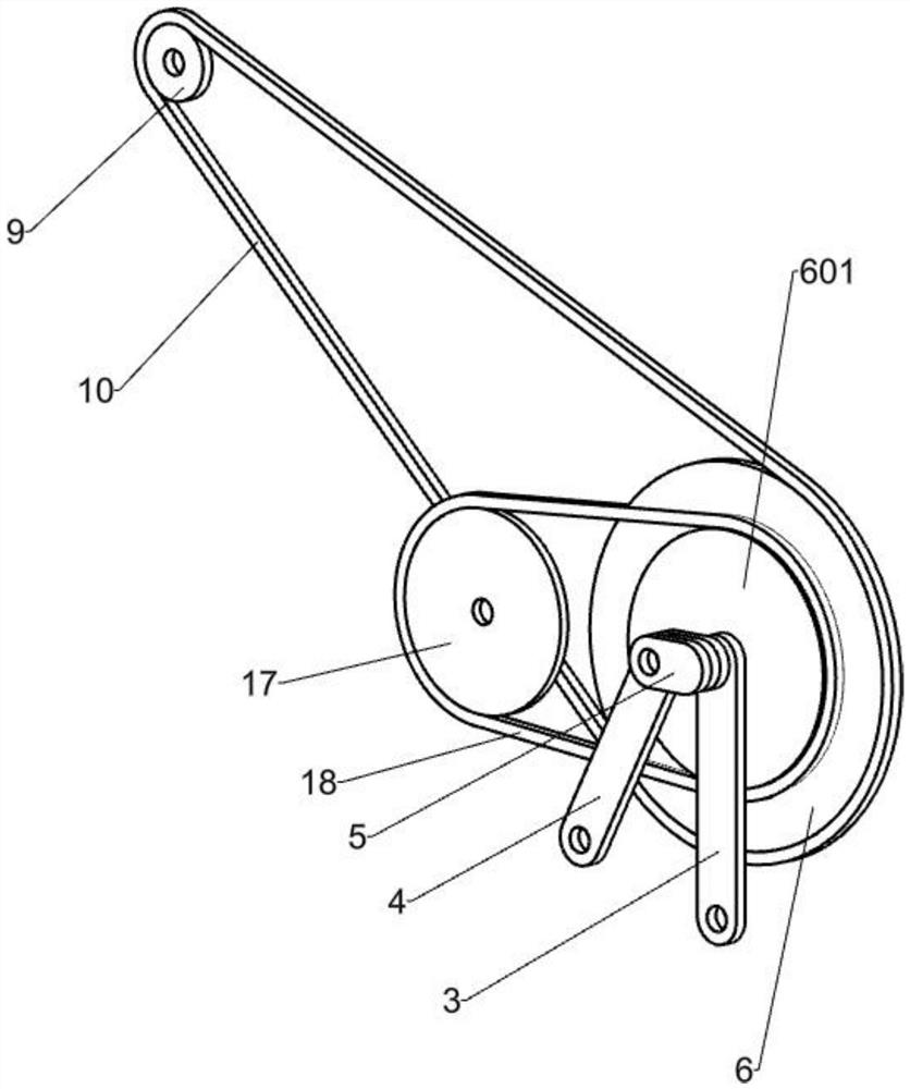
[0069] Construction garbage collection waste wire packaging device, such as Figure 1-9 As shown, including the first bracket 1, the pedal 2, the link one 3, the link two 4, the link three 5, the second drive wheel 601, the first transmission wheel 6, the second bracket 7, fixed bracket 8, small The pulley 9, the conveyor belt 10 and the rolling member, the pedal 2 is rotated to be connected to the left and right side of the first bracket, and the link one 3 is hinged on the right side of the pedal 2, and the link two 4 is hinged on the right side of the pedal 2, and the link is two. 4 Located behind the link one 3, the connecting rod three 5 hinged link one 3 is above the link 4, and the link two 4 is connected to the second drive wheel 601, and the first shift wheel 6 is secured to the second drive wheel. On the right side of the 601, the second bracket 7 is fixed to the first bracket 1, and the fixing bracket 8 is fixed to the second bracket 7, and the small pulley 9 is rotated ...

Embodiment 2

[0072] On the basis of Example 1, such as Figure 2-4 As shown, the rolling member includes a first transport shaft 11, a pinion 12, a rack fixing frame 13, a notch ring rack 14, and a tape placed block 15, and the first drive shaft 11 is secured to a small pulley through a fixed bracket 8. 9, the pinion gear 12 is fixed to the first transmitting shaft 11 end, and the rack fixing frame 13 is fixed to the left side of the second bracket 7, and the first transfer shaft 11 is placed above the rack fixing frame 13, the gap ring teeth The strip 14 is rotated within the rack fixing frame 13, and the pinion gear 12 is engaged with the gap ring zip 14, and the tape placed block 15 is fixed to the left side of the gap ring rack 14.

[0073] When packaged to the building, manual will be placed in the center position of the raw building 13, and then paste one end on the tape on the tape placed block 15, and the artificial foot pedal 2 rotates. The hand pushed the rolled construction, and the ...

Embodiment 3

[0075] On the basis of Example 2, such as Figure 2-9 As shown, there are three limit sliding assemblies, and the three limit sliding assemblies include a fixed base 16, a fixed cover 161, and a pulley 162, wherein the two fixed bases 16 are fixed above the first bracket, a fixed base 16. Following the second bracket 7, the fixing cover 161 is hinged to the fixed base 16, the pulley 162 is a pair, and the pulley 162 is rotated within the fixed base 16, and the pulley 162 is close to the fixed cover 161.

[0076] When packaging the building, artificially open three fixed cover 161, then put the rolled building waste line in the outer edge of the building, the outer edge of the building is in contact with the pulley 162, and manually will fix the fixed cover 161 cover, into the building The abandoned wire is fixed to a circle, artificial foot pedal 2, and the hand push-to-line construction waste line movement, and the outer edge of the building is sliding, the tape placed block 15 Th...


PUM


Abstract

The invention relates to a packing device, in particular to a waste wire packing device for recycling construction waste. The technical problem to be solved by the present invention is to provide a foot-operated waste wire packaging device for construction field that can not only exercise the body, but also pack the waste wire in batches. In order to solve the above technical problems, the present invention provides such a waste wire packaging device for recycling construction waste, which includes a first bracket, a pedal, a connecting rod one, a connecting rod two, a connecting rod three, a second transmission wheel, a first transmission Wheel, second bracket, fixed bracket, small pulley, conveyor belt one and rolling parts, the pedal is rotatably connected to the left and right sides of the first bracket, connecting rod one is hinged on the right side of the pedal, and connecting rod two is hinged on the right side of the pedal. Rod 2 is located behind connecting rod 1. The present invention has the function of limiting sliding. By manually pushing the rolled construction waste line to move, the outer edge of the rolled building waste line slides with the pulley, thereby achieving the effect of limited sliding.

Description

Technical field [0001] The present invention relates to a packaging apparatus, and more particularly to a waste wire packaging apparatus for construction waste recovery. Background technique [0002] The construction waste line is packaged, and the construction waste line can be treated into construction aggregates that can be used for specific projects and recycled materials, waste wires, and various scrap parts, sorting, concentrated, in the steel plant. Processed into a variety of steels. [0003] Before the construction of the construction, it is artificial to take the loose abandon line to make the loose abandon line, and then the construction waste line is quickly placed in the rotating shaft. The tape is entangled. Waste lines are winding, there is a safety hazard, and this complicated operation will increase the amount of packing belt. [0004] In response to the above problems described above, the problem of packaging the construction of the wire, therefore, there is an ...

Claims


Application Information

Patent Timeline
Patent Type & Authority Patents(China)
IPC IPC(8): B65B27/06B65B13/16B65B13/18
CPCB65B27/06B65B13/16B65B13/18
Inventor 吴月艳
Owner 环创(赤峰)科技有限公司
Why Eureka
Try Eureka