Ultrahigh vacuum pneumatic gate valve

An ultra-high vacuum, plug-in valve technology, used in sliding valves, valve details, valve devices, etc., can solve problems such as large vibration and noise, reduce vibration and noise, reduce production costs, and ensure size and parallelism. Effect

Active Publication Date: 2020-09-25
CHENGDU ZHONGKE WISH INSTR CO LTD
View PDF11 Cites 0 Cited by
  • Summary
  • Abstract
  • Description
  • Claims
  • Application Information

AI Technical Summary

Problems solved by technology

[0008] Based on the above problems, the object of the present invention is to provide an ultra-high vacuum pneumatic flapper valve, which is used to solve the problem that the flapper valve in the prior art will generate relatively large vibration and noise when it is working.

Method used


Image

  • Ultrahigh vacuum pneumatic gate valve
  • Ultrahigh vacuum pneumatic gate valve
  • Ultrahigh vacuum pneumatic gate valve

Examples


Embodiment 1

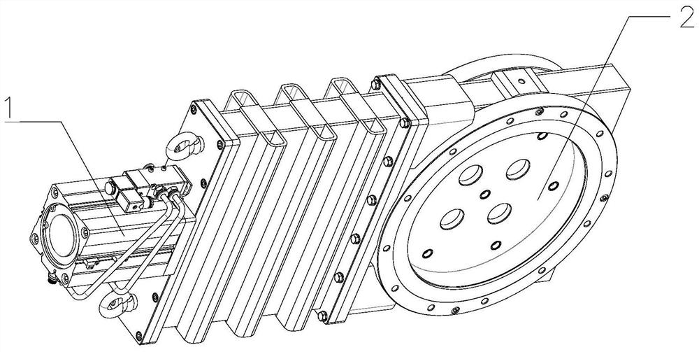
[0047] like Figure 1-7 As shown, an ultra-high vacuum pneumatic flapper valve includes a valve body 2 and a pneumatic propulsion mechanism 1, the pneumatic propulsion mechanism 1 includes a cylinder barrel 3, and a cylinder front end cover 10 and a cylinder piston 12 are installed in the cylinder barrel 3, the cylinder A bellows connecting rod 7 is connected to the piston 12, a guiding mechanism is connected to the bellows connecting rod 7, a cylinder connecting plate 6 is connected to the front end of the cylinder barrel 3, and a front buffer is installed on the side of the cylinder connecting plate 6 close to the guiding mechanism. Mechanism, a rear buffer mechanism is installed on the side of the cylinder piston 12 close to the front end cover 10 of the cylinder; the valve body 2 includes a closing plate 15 and a supporting plate 13, and ball sockets 22 are opened on the opposite surfaces of the closing plate 15 and the supporting plate 13, Two connection plates 14 paralle...

Embodiment 2

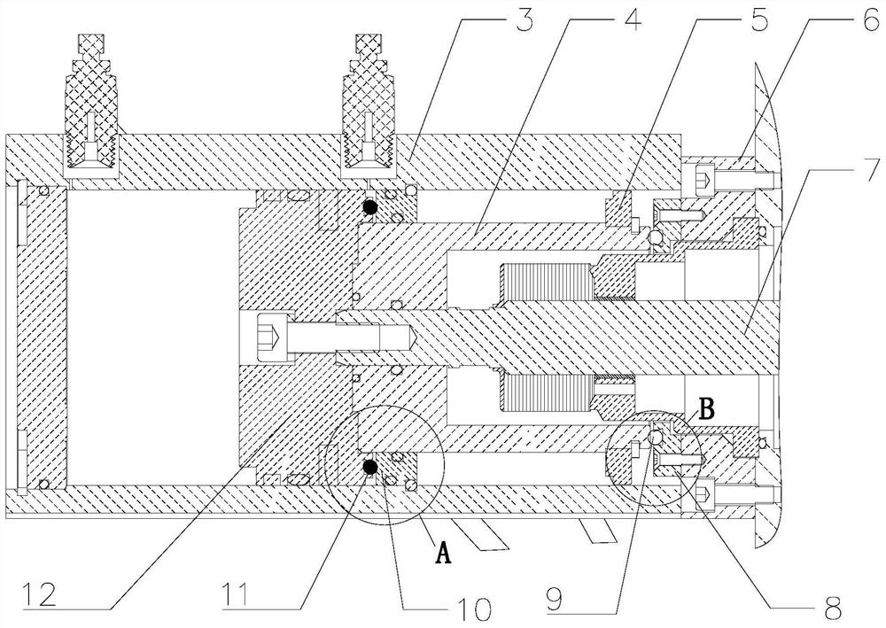
[0051] like Figure 1-2 As shown in and 14-15, on the basis of the above-mentioned embodiment 1, this embodiment provides some preferred technical features of the pneumatic propulsion mechanism. That is, the guide mechanism includes a guide cylinder 4 installed on the bellows connecting rod 7 , and a guide ring 5 is installed on the circumferential surface of the guide cylinder 4 . The cylinder guide cylinder 4 and the guide ring 5 are added for more stable guidance during the movement of the cylinder, so the stability and reliability of the vacuum valve during opening and closing can be improved.

[0052] The front buffer mechanism includes a buffer ring 8 installed on the side of the cylinder connecting plate 6, and a front buffer rubber pad 9 is installed on the buffer ring 8, and the cylinder connecting plate 6 and the buffer ring 8 are connected by screws, and the side of the buffer ring 8 has a front installation Groove 21, the front buffer rubber pad 9 is installed in ...

Embodiment 3

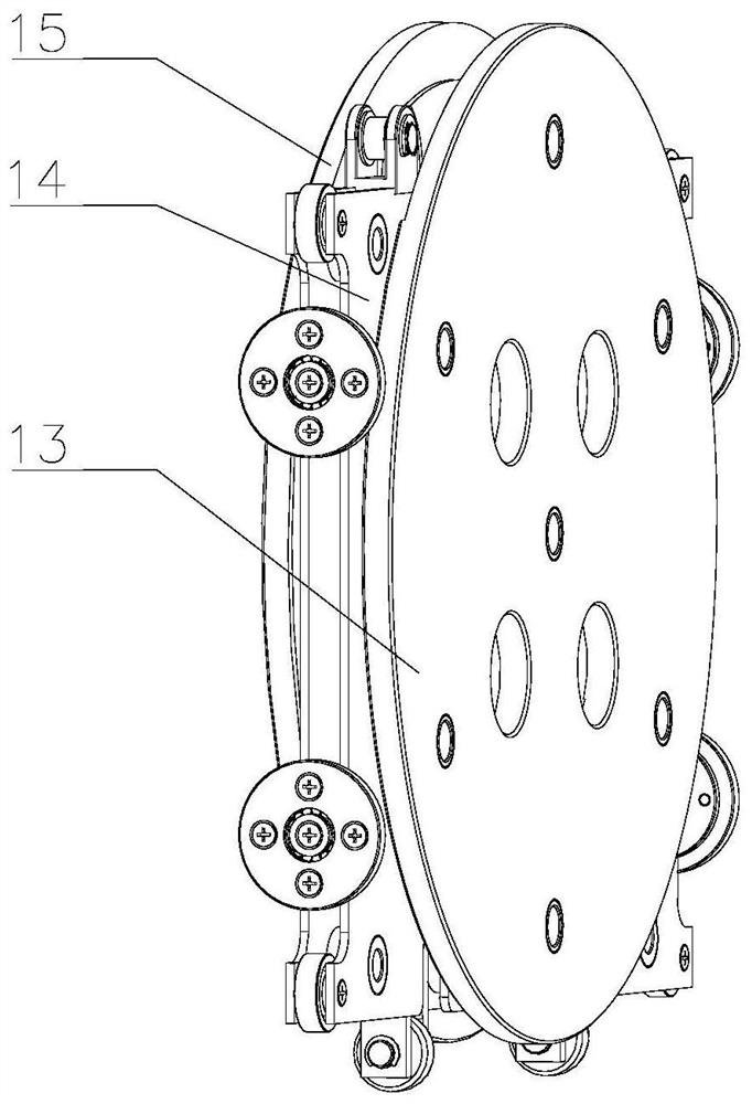
[0054] like Figure 3-13 As shown, on the basis of the above-mentioned embodiment 1, this embodiment provides some preferred technical features of the valve core. That is to say, the damping mechanism includes mounting grooves 21 opened on the opposite surfaces of the closing plate 15 and the support plate 13, two connecting plates 14 are provided with waist-shaped holes 141 corresponding to the mounting grooves 21, and the two opposite mounting grooves 21 Buffer tubes 16 passing through the waist-shaped holes 141 are respectively installed inside, and buffer springs 17 are installed between the two opposite buffer tubes 16 . The buffer spring 17 is installed in the guide groove 162, and the buffer cylinder 16 includes an installation body 161 and a guide body 163 formed integrally with each other. The diameter of the installation body 161 is larger than that of the guide body 163, and a plurality of connection holes 1611 are provided on the installation body 161. , the mount...


PUM


Abstract

The invention relates to the technical field of vibration reduction of gate valves, in particular to an ultrahigh vacuum pneumatic gate valve. The ultrahigh vacuum pneumatic gate valve is used for solving the problem that in the prior art, large vibration and noise are generated to a gate valve during work. The ultrahigh vacuum pneumatic gate valve comprises a valve body and a pneumatic pushing mechanism. The pneumatic pushing mechanism comprises an air cylinder barrel, an air cylinder front end cover, an air cylinder piston, a corrugated pipe connecting rod and an air cylinder connecting plate. A front buffer mechanism is mounted on the air cylinder connecting plate, and a rear buffer mechanism is mounted on the side, close to the air cylinder front end cover, of the air cylinder piston.The valve body comprises a closing plate, a supporting plate, a ball socket, a connecting plate, a steel ball sleeve and a steel ball. Multiple vibration reduction mechanisms are mounted between the closing plate and the supporting plate. In the ultrahigh vacuum pneumatic gate valve, through the front buffer mechanism and the rear buffer mechanism, vibration and noise generated when the pneumaticpushing mechanism is closed can be effectively reduced; and through the vibration reduction mechanisms, valve element vibration and noise generated when the steel ball returns back into the ball socket can be reduced, and therefore vibration and noise of the gate valve can be overall reduced.

Description

technical field [0001] The invention relates to the technical field of damping of a gate valve, and more specifically relates to an ultra-high vacuum pneumatic gate valve. Background technique [0002] The gate valve is a component of the vacuum valve used to adjust the air flow, cut off or connect the pipeline. The flapper valve in the prior art includes a valve body and a pneumatic propulsion mechanism. Flanges are installed on the two opposite outer surfaces of the valve body. The valve body has two coaxial valve ports. The mechanism is connected with the valve core through the connecting mechanism, and the valve core is often pushed to the valve port through the cylinder shaft or hinge mechanism, and then the valve port is sealed by the cam pressing the closing plate, and the fluid cannot pass through the pipeline at this time; or through the cylinder shaft or hinge The mechanism drives the valve core away from the valve port, at this time, the fluid can pass through th...

Claims


Application Information

Patent Timeline
Patent Type & Authority Applications(China)
IPC IPC(8): F16K3/02F16K3/314F16K31/122F16K47/02F16F15/08
CPCF16K3/0218F16K3/314F16K31/122F16K47/02F16F15/085
Inventor 张军王小军魏琼林赵红斌贺云凡周阳
Owner CHENGDU ZHONGKE WISH INSTR CO LTD
Why Eureka
Try Eureka