Building measuring instrument

A technology for measuring instruments and buildings, applied in the directions of instruments, measuring devices, radio wave measuring systems, etc., can solve the problems of data deviation, prolongation of receiving time, and longer distance of laser beam emission, so as to achieve accurate data and improve the level of state. , Improve the effect of firm stability

Inactive Publication Date: 2020-09-25
广州比美强机械技术开发有限公司
View PDF0 Cites 0 Cited by
  • Summary
  • Abstract
  • Description
  • Claims
  • Application Information

AI Technical Summary

Problems solved by technology

[0002] The laser rangefinder measures the distance inside the building room during the construction process. The laser rangefinder emits a laser beam, and the photoelectric element receives the laser beam reflected by the target. The timer measures the time from the launch to the reception of the laser beam, so that Calculate the target distance, but when the laser distance measuring instrument is working, the laser beam must be emitted horizontally. Because the interior of the construction site room is affected by the unstable ground and there are many fine sand and stones on the ground, the laser distance measuring instrument is easy to A certain horizontal angle deviation occurs, which makes the distance of the laser beam longer, causing the time for the timer to measure the laser beam to be extended from emission to reception, resulting in a certain deviation in the data calculated from the target distance

Method used


Image

  • Building measuring instrument
  • Building measuring instrument
  • Building measuring instrument

Examples


Embodiment 1

[0024] as attached figure 1 to attach Figure 6 Shown:

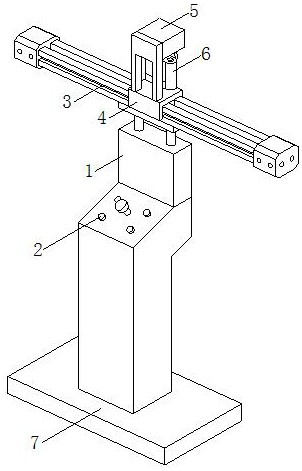
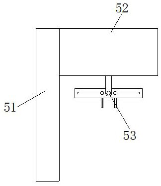
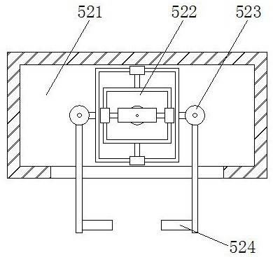
[0025] The present invention is a building surveying instrument, its structure includes a support platform 1, a control button 2, a conductive slide rail 3, a sliding block 4, a balance bracket 5, a laser distance measuring instrument 6, a balance base 7, the upper surface of the support platform 1 is embedded There is a control button 2, the upper end of the support table 1 is fixedly equipped with a conduction slide rail 3, the outer surface of the conduction slide rail 3 is slidably connected with the inner side of the slide block 4, and the upper surface of the slide block 4 is fixed with the bottom of the balance bracket 5, The balance bracket 5 is connected to the upper end of the laser distance measuring instrument 6, and the bottom of the support platform 1 is welded to the upper surface of the balance base 7. The balance bracket 5 includes a support frame 51, a balance connector 52, and a clamp 53. The lower e...

Embodiment 2

[0033] as attached Figure 7 To attach Figure 8 Shown:

[0034] Wherein, the balance base 7 includes a base plate 71, telescopic feet 72, connecting plates 73, telescopic hoses 74, and an air blowing mechanism 75. Inside the lower end of the bottom plate 71, the upper end of the telescopic foot 72 is welded to the bottom surface of the connecting plate 73, and the connecting plate 73 is installed inside the lower end of the bottom plate 71 by clearance fit, and the upper surface of the connecting plate 73 is fixed to the lower end of the telescopic hose 74, The upper end of the telescopic hose 74 communicates with the air blowing mechanism 75, and the air blowing mechanism 75 is fixedly installed on the inner top of the bottom plate 71. The telescopic feet 72 are provided with eighteen pieces, and nine of them form a group, and are installed on the bottom plate respectively. The front and rear sides of 71 are conducive to supporting the base plate 71. The telescopic hoses 7...


PUM


Abstract

The invention discloses a building measuring instrument, which structurally comprises a supporting table, control buttons, conduction sliding rails, a sliding block, a balance bracket, a laser distance measuring instrument and a balance base, wherein the control buttons are embedded in the upper end surface of the supporting table. According to the invention, magnetisms of magnetic blocks arrangedon clamping plates on the two sides are opposite to improve magnetic adsorption between the clamping plates on the two sides, so that the firmness and the stability of clamping a laser distance measuring instrument by the clamping plates are improved; and a rotor rotates, and outer ring torquers at the upper and lower ends of an outer ring are relatively kept balanced, so that the laser distancemeasuring instrument is kept on the horizontal line, and a laser beam on the laser distance measuring instrument is ensured to be emitted horizontally; a telescopic hose shrinks to achieve a certain buffering effect while the telescopic hose conducts air pressure, at the moment, a pressure dividing groove conducts the air pressure into eight pressure discharging pipes, inclined air spraying is conducted towards the outer side of a bottom plate through an air outlet end of a nozzle, fine sand and stones at the lower end of the bottom plate are blown out, and the horizontal state of the laser distance measuring instrument is improved.

Description

technical field [0001] The invention relates to the field of instruments and meters, and more specifically relates to a building measuring instrument. Background technique [0002] The laser rangefinder measures the distance inside the building room during the construction process. The laser rangefinder emits a laser beam, and the photoelectric element receives the laser beam reflected by the target. The timer measures the time from the launch to the reception of the laser beam, so that Calculate the target distance, but when the laser distance measuring instrument is working, the laser beam must be emitted horizontally. Because the interior of the construction site room is affected by the unstable ground and there are many fine sand and stones on the ground, the laser distance measuring instrument is easy to A certain horizontal angle deviation occurs, which makes the distance of the laser beam longer, which causes the time for the timer to measure the laser beam to be exte...

Claims


Application Information

Patent Timeline
IPC IPC(8): G01S17/08G01S7/481A47L11/24A47L11/40
CPCA47L11/24A47L11/40A47L11/4036G01S7/481G01S17/08
Inventor 陈雪莲
Owner 广州比美强机械技术开发有限公司
Why Eureka
Try Eureka