
Defogging glasses

A technology for glasses and defogging, applied in the field of glasses

Inactive Publication Date: 2020-09-25
ANHUI POLYTECHNIC UNIV MECHANICAL & ELECTRICAL COLLEGE
View PDF0 Cites 1 Cited by
  • Summary
  • Abstract
  • Description
  • Claims
  • Application Information

AI Technical Summary

Problems solved by technology

However, wearing glasses has also brought great inconvenience to life, the most troublesome thing is the layer of mist on the glasses

Method used


Image

  • Defogging glasses

Examples


Embodiment Construction

[0020] Specific embodiments of the present invention will be described in detail below in conjunction with the accompanying drawings. It should be understood that the specific embodiments described here are only used to illustrate and explain the present invention, and are not intended to limit the present invention.

[0021] In the present invention, unless otherwise specified, the orientation words included in the term such as "up, down, left, right, front, back, inside and outside" only represent the orientation of the term in the normal use state, or the common name understood by those skilled in the art. , and should not be construed as a limitation of this term.

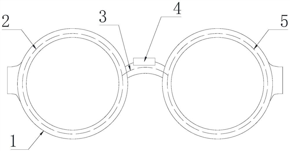
[0022] see figure 1 The defogging glasses shown in the figure comprise a glasses body, on which a left-right symmetrical lens frame 1 is arranged, and a first electric heating wire 2 and a second electric heating wire 2 are arranged in the two lens frames 1 respectively. Heating wire 5, a nose pad is arranged...


PUM


Abstract

The invention discloses a pair of defogging glasses. The pair of defogging glasses comprises a glasses body, lens frames which are in bilateral symmetry are arranged on the glasses body, a first electric heating wire and a second electric heating wire are arranged in the two lens frames respectively, a nose pad is arranged between the two lens frames, a wire and a heating mechanism are arranged inthe nose pad, and the heating mechanism is electrically connected to the first electric heating wire and the second electric heating wire through the wire respectively. The surrounding environment ofthe lenses of the defogging glasses can be heated to avoid fogging.

Description

technical field [0001] The present invention relates to glasses, in particular to defogging glasses. Background technique [0002] In today's society, due to the continuous appearance of electronic products and the continuous increase of academic pressure, more and more people have myopia, and a group of people who wear glasses have appeared. However, wearing glasses has also brought great inconvenience to life, and the most troublesome thing is the mist on the glasses. I believe that every compatriot who wears glasses has experienced such embarrassment in winter. When drinking hot water or eating hot pot, the glasses fog up. [0003] Every winter, the biggest worry for friends who wear glasses is fogging of the glasses. Especially in cold weather, the phenomenon of lens fogging is more obvious, seriously affecting vision, which cannot be ignored in life and work. In response to this problem, the idea of ​​​​adding a defogging function to glasses was born. Contents of t...

Claims


Application Information

Patent Timeline
IPC IPC(8): G02C11/08
CPCG02C11/08
Inventor 赵先跃
Owner ANHUI POLYTECHNIC UNIV MECHANICAL & ELECTRICAL COLLEGE
Learn More