Simplification method of fuel cell stack fluid simulation model

A fuel cell and fluid simulation technology, applied in fuel cells, fuel cell additives, fuel cell control, etc., can solve problems such as large deviation and pressure drop

Active Publication Date: 2020-09-25
北京新研创能科技有限公司
View PDF15 Cites 5 Cited by
  • Summary
  • Abstract
  • Description
  • Claims
  • Application Information

AI Technical Summary

Problems solved by technology

However, compared with the original model, the calculated pressure drop of the single-plate model using this simplified method is too low, resulting in large deviations from the original model in the calculation results of flow distribution and overall pressure drop

Method used


Image

  • Simplification method of fuel cell stack fluid simulation model
  • Simplification method of fuel cell stack fluid simulation model
  • Simplification method of fuel cell stack fluid simulation model

Examples


no. 1 example

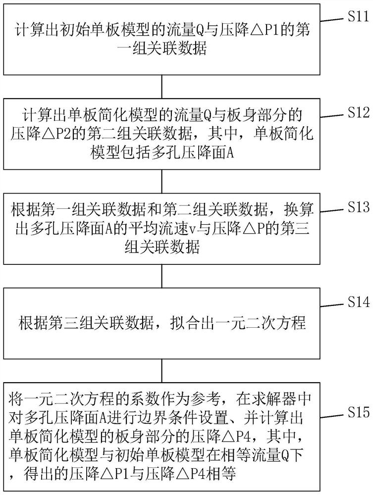
[0050] Please refer to figure 1 , the present embodiment provides a simplified method for a fuel cell stack fluid simulation model, the method includes the following steps:

[0051] S11: Calculate the first set of associated data between the flow rate Q and the pressure drop ΔP1 of the initial single plate model.

[0052] Specifically, by performing flow field simulation on the initial veneer model, at least five sets of calculation results of the corresponding pressure drop △P1 under different flow rates Q are obtained, and at least five sets of associated data between the flow rates Q and the pressure drop △P1 form the first set of associations data.

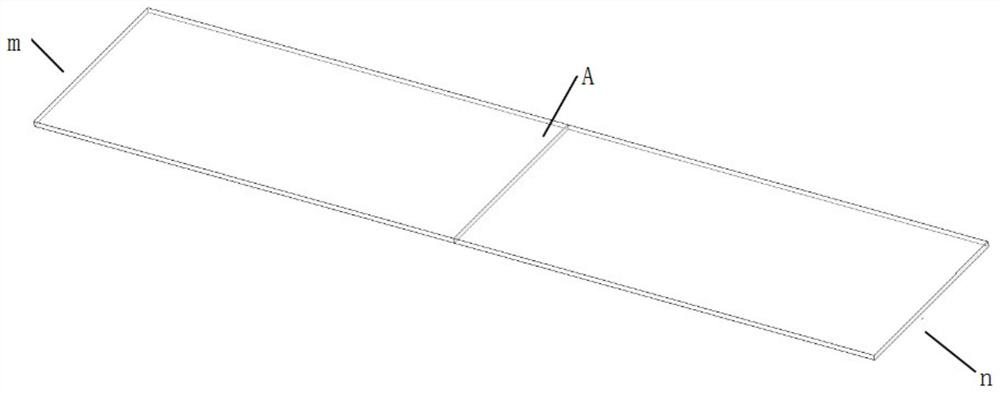
[0053]S12: Calculate the second set of associated data between the flow rate Q of the simplified model of the single plate and the pressure drop ΔP2 of the plate body, wherein the simplified model of the single plate includes a porous pressure drop surface A.

[0054] Specifically, first, see figure 2 , establish a simplif...

no. 2 example

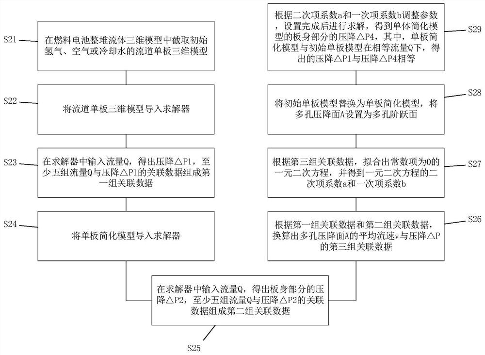
[0072] Please refer to image 3 , the present embodiment provides a simplified method for a fuel cell stack fluid simulation model, the method includes the following steps:

[0073] S21: Intercept the three-dimensional model of the flow channel single plate of initial hydrogen, air or cooling water in the three-dimensional model of the whole stack fluid of the fuel cell.

[0074] S22: importing the three-dimensional model of the runner single plate into the solver.

[0075] Specifically, first, mesh the 3D model of the runner veneer; then, import the 3D model of the runner veneer containing the mesh into the solver; finally, set the boundary conditions for the 3D model of the runner veneer in the solver .

[0076] S23: Input the flow Q into the solver to obtain the pressure drop ΔP1, and at least five sets of associated data of the flow Q and the pressure drop ΔP1 form the first set of associated data.

[0077] Specifically, at least five sets of calculation results of pres...


PUM


Abstract

The invention provides a simplification method of a fuel cell stack fluid simulation model. The method comprises the following steps: calculating a first group of associated data of flow Q and pressure drop [Delta]P1 of an initial single board model; calculating a second group of associated data of the flow Q of the plate body part of the single-plate simplified model and the pressure drop [Delta]P2, wherein the single-plate simplified model comprises a porous pressure drop surface A; according to the first group of associated data and the second group of associated data, converting to obtaina third group of associated data of the average flow velocity v of the porous pressure drop surface A and the pressure drop [Delta]P; fitting a unary quadratic equation according to the third group ofassociated data; and taking the coefficient of the unary quadratic equation as a reference, setting boundary conditions for the porous pressure drop surface A in a solver, and calculating the pressure drop [Delta]P4 of the single-board simplified model, the single-board simplified model and the initial single-board model being under the condition of equal flow Q, and the obtained pressure drop [Delta]P1 and pressure drop [Delta]P4 being equal. According to the method, the accuracy of whole-pile flow distribution and pressure drop simulation calculation can be improved.

Description

technical field [0001] The invention relates to the technical field of fuel cells, in particular to a simplified method for a fuel cell whole stack fluid simulation model. Background technique [0002] During the operation of the fuel cell stack, the uniformity of fluid distribution on each hydrogen, air and cooling water fluid single plate is an important factor affecting the overall performance. In the pre-design process of the fuel cell stack, CFD simulation is usually used to optimize the flow distribution of the whole stack. However, since the entire fluid model includes multiple single-plate models with complex structures, if the initial model is used for simulation calculation, the number of grids will be too large, the computer memory load will be large, and the calculation will be difficult or even impossible. Existing fuel simulation methods usually simplify the single-plate flow channel model to a thin-layer plate for simulation, which can effectively reduce the ...

Claims


Application Information

Patent Timeline
Patent Type & Authority Applications(China)
IPC IPC(8): G06F30/20G06F17/11H01M8/04298G06F113/08
CPCG06F30/20G06F17/11H01M8/04305G06F2113/08Y02E60/50
Inventor 韩婷婷张旭
Owner 北京新研创能科技有限公司
Why Eureka
Try Eureka