
Contact system of switching device

A technology of a contact system and a switch device, applied in the field of contact systems, can solve the problems of large internal space and inability to use the switch, and achieve the effect of solving the layout, reducing parts, and small space.

Pending Publication Date: 2020-09-25
上海瑞忒尔电气技术有限公司 +1
View PDF0 Cites 0 Cited by
  • Summary
  • Abstract
  • Description
  • Claims
  • Application Information

AI Technical Summary

Problems solved by technology

[0003] At present, the contact system of the switch device occupies a large space inside the switch and cannot be used in a narrow and long space. Therefore, we propose a contact system of the switch device to solve the above disadvantages

Method used


Image

  • Contact system of switching device
  • Contact system of switching device
  • Contact system of switching device

Examples


Embodiment

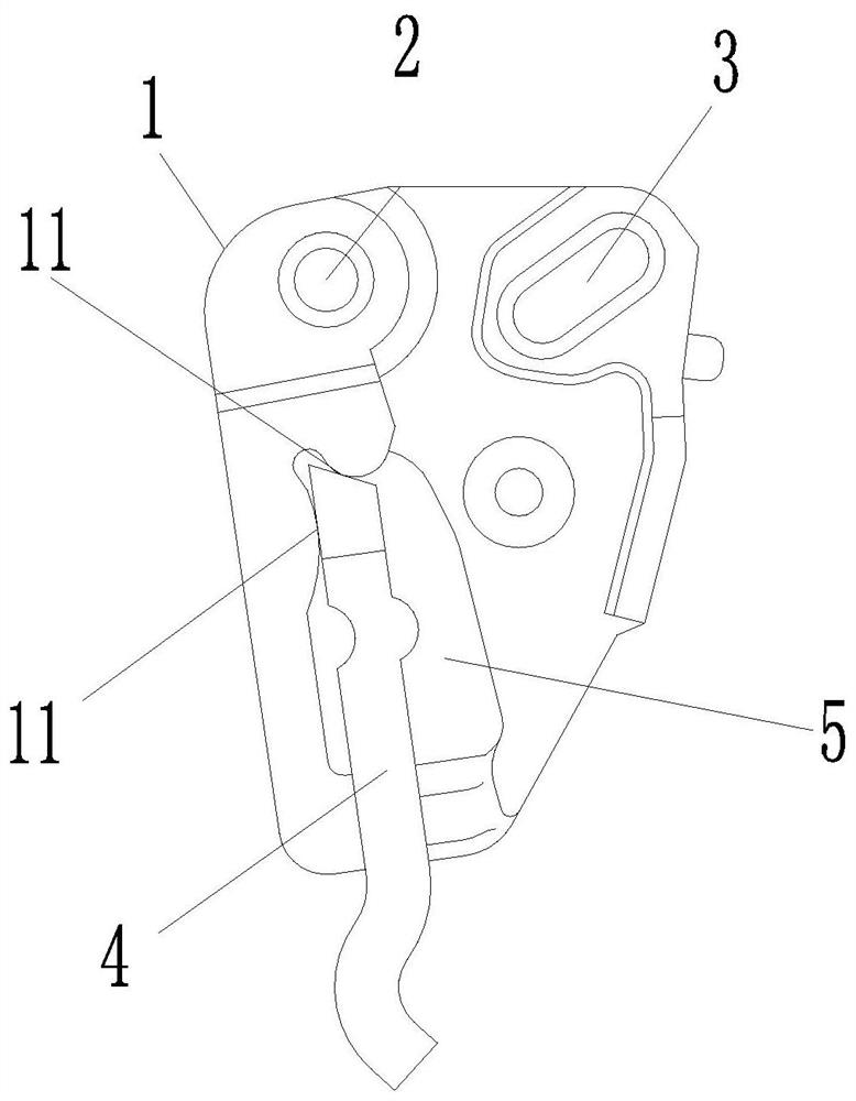
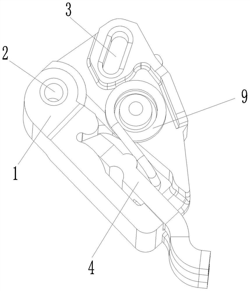
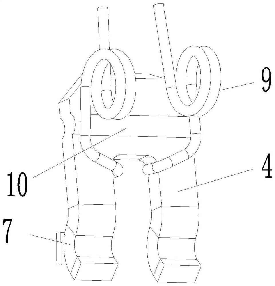
[0021] Example: see Figures 1 to 5 , the present invention provides a technical solution: a contact system of a switch device, including: a support 1, a support point rotation point 2 for connecting the switch main body is provided on the support 1, and a support for connecting the switch is provided on the support 1 The chute 3 of the operating mechanism, the side of the support 1 away from the rotation point 2 of the support is movably connected with the movable contact 4, and the support 1 is provided with a receiving groove 5 for transferring the movable contact 4, and one end of the movable contact 4 Inserted into the receiving groove 5, the other end of the movable contact 4 is provided with a conductive plate 6 for use with it.

[0022] Among them, the movable contact 4 is in the shape of n as a whole, and the side of the movable contact 4 is flat, and one end of the opening of the movable contact 4 is integrally formed with two arc-shaped movable contacts 7, and the c...


PUM


Abstract

The invention relates to the technical field of low-voltage electric appliances, particularly to a contact system of a switching device. The contact system comprises a support piece, which is providedwith a supporting point rotating point used for being connected with a switch body, and is provided with a sliding groove used for connecting a switch operation mechanism, wherein a moving contact ismovably connected to one side, far away from the support piece rotating point, of the support piece, the support piece is provided with an accommodating groove used for matching with the moving contact, one end of the moving contact is inserted into the accommodating groove, and the other end of the moving contact is provided with a conductive plate used in cooperation with the moving contact. According to the invention, parts needed by rotation can be effectively reduced while the space occupied by the contact system in the switch is small, so that the size of the switch device can be reduced so as to solve the problem that the contact system is arranged in a long and narrow space.

Description

technical field [0001] The invention relates to the technical field of low-voltage electrical appliances, in particular to a contact system of a switch device. Background technique [0002] The word switch is interpreted as turning on and off. It also refers to an electronic component that can open a circuit, interrupt the current, or cause it to flow to other circuits. The most common switch is an electromechanical device that is operated by a person. One or more Electronic contacts. The "closed" of the contact means that the electronic contact is conductive and allows current to flow; the "open circuit" of the switch means that the electronic contact is not conductive to form an open circuit and does not allow current to flow. [0003] At present, the contact system of the switch device occupies a large space inside the switch, and cannot be used in a narrow and long space. Therefore, we propose a contact system of the switch device to solve the above disadvantages. Con...

Claims


Application Information

Patent Timeline
Patent Type & Authority Applications(China)
IPC IPC(8): H01H1/22H01H1/24H01H1/58
CPCH01H1/221H01H1/24H01H1/58H01H2001/223
Inventor 王斌付志军李阳智周文静
Owner 上海瑞忒尔电气技术有限公司
Learn More