
Feeding and discharging device applied to threading machine

A wire threading machine and feeding technology, applied in the direction of thread cutting device, thread cutting feeding device, metal processing equipment, etc., can solve the problems of time-consuming and laborious, manual loading and unloading, etc., to improve work efficiency, increase stability, The effect of reducing the possibility of different tube lengths

Active Publication Date: 2020-09-29
杭州永恒钢结构有限公司
View PDF8 Cites 0 Cited by
  • Summary
  • Abstract
  • Description
  • Claims
  • Application Information

AI Technical Summary

Problems solved by technology

[0004] When using the threading machine in the prior art, the worker inserts the pipe material into the rear chuck and the front chuck, first cuts the pipe material through the cutter, and then processes the pipe material with the die plate device, and finally the scraper performs the reverse corner, and then remove the pipe material from the rear chuck and front chuck, but in actual production, workers need to manually load and unload the material for a long time, which is time-consuming and laborious, and needs to be improved

Method used


Image

  • Feeding and discharging device applied to threading machine
  • Feeding and discharging device applied to threading machine
  • Feeding and discharging device applied to threading machine

Examples


Embodiment

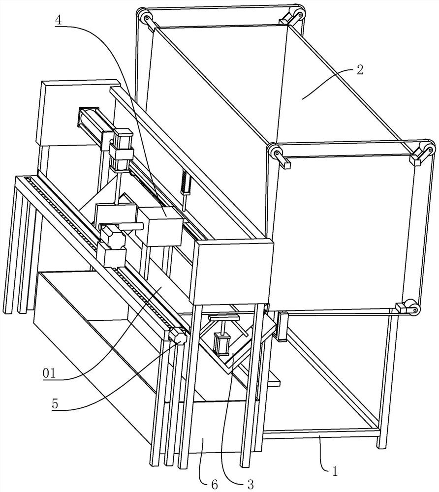
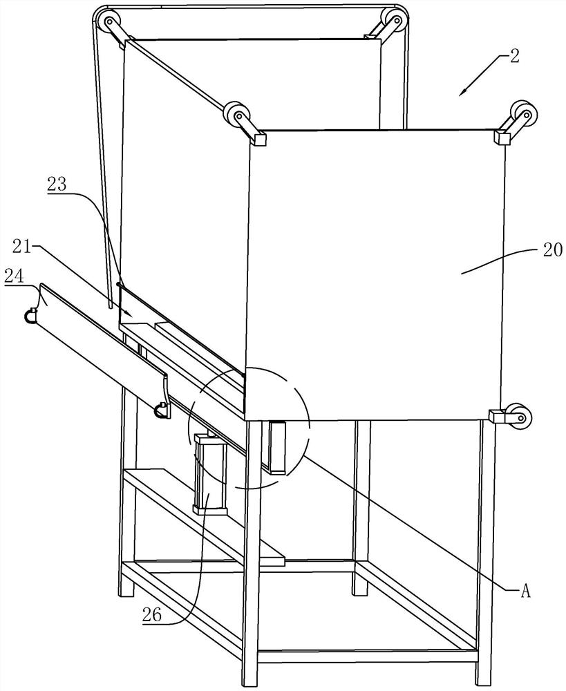
[0043] refer to figure 1 , a loading and unloading device applied to threading machines, which includes a frame 1, which is provided with a storage box 2 for outputting pipe materials 01 one by one, on the frame 1 and located at the storage box 2 One side is provided with a material storage frame 3, and a material receiving box 6 is provided under the material storage frame 3. The frame 1 is respectively provided with clamping parts 4 for clamping the tube material 01 and for driving the tube material 01 to move in and out. The power assembly 5 of the threading machine, the clamping part 4 is arranged on the power assembly 5, and the power assembly 5 is located on the side of the storage rack 3 away from the storage box 2; firstly, put a plurality of pipe materials 01 into the storage box 2 , during processing, the storage box 2 outputs the pipe material 01 one by one, the pipe material 01 slides onto the material rack 3, the clamping part 4 clamps the pipe material 01, and th...


PUM


Abstract

The invention discloses a feeding and discharging device applied to a threading machine, and relates to auxiliary equipment of the threading machine. The feeding and discharging device aims to solve the problem that the threading machine in the prior art needs manual feeding and discharging by workers. According to the technical scheme, the feeding and discharging device is characterized by comprising a rack, wherein a material storage box, a material containing frame, a clamping piece and a power assembly are arranged on the rack correspondingly; and the clamping piece is arranged on the power assembly, and a material receiving box is arranged below the material containing frame. When pipe materials need to be machined, a single pipe material is moved out of the material storage box, after the material containing frame bears the pipe material, the clamping piece clamps the pipe material, and the power assembly drives the clamping piece and the pipe material to move forwards so that the pipe material can be inserted into the threading machine; and after the threading machine machines the pipe material, the pipe material is clamped by the clamping piece, the power assembly drives the clamping piece and the pipe material to move out of the threading machine, the material containing frame outputs the pipe material again, and the pipe material finally enters the material receivingbox so that the working mode of manual feeding and discharging by the workers can be replaced, the workload of the workers is relieved, and the working efficiency is improved.

Description

technical field [0001] The invention relates to an auxiliary device of a threading machine, more specifically, it relates to a loading and unloading device applied to a threading machine. Background technique [0002] Threading machine is also known as electric threading machine, electric pipe cutting machine, wire twisting machine, pipe threading machine, steel bar threading machine. The threading machine can thread pipes, bars, and steel bars. Specifically, it electrifies the traditional manual pipe thread twister, which makes the pipe thread processing during pipeline installation easy and fast, and reduces the labor of pipeline installation workers. strength. The threading machine is composed of: machine body, motor, reduction box, pipe chuck, die head, cutter holder, feeding device, and cooling system. [0003] The Chinese patent with authorized notification number CN205362895U discloses a new type of threading machine, including a threading machine base, a frame is i...

Claims


Application Information

Patent Timeline
IPC IPC(8): B23G11/00
CPCB23G11/00Y02P70/10
Inventor 丁一东丁利文
Owner 杭州永恒钢结构有限公司
Learn More