An injection molding device for plastic pipe clamps

A plastic tube and injection molding technology, applied in the field of injection molding equipment, can solve problems such as deformation, damage, and flow marks of injection molding products, and achieve the effects of ensuring quality, avoiding flow marks, and long service life

Active Publication Date: 2021-11-16
芜湖富田电子科技有限公司
View PDF0 Cites 0 Cited by
  • Summary
  • Abstract
  • Description
  • Claims
  • Application Information

AI Technical Summary

Problems solved by technology

[0003] Our company has used this type of injection molding machine to inject plastic pipe clips for a long time, and found that the existing injection molding device still has the following disadvantages: 1. The size of the gate should be designed according to the situation of the product. It cannot be changed, but during the injection molding process, when the plastic pipe clamp is filled into the internal thread, the melt will diverge. Part of the melt fills into the thread part structure horizontally, and other parts of the melt still fill vertically to the appearance of the product, resulting in horizontal The amount of flowing glue is reduced, so the flow mark problem will occur due to the change of the flow state of the melt in this transition section; 2. The gate of a single-size mold is used for a long time, due to the small stress area and strong pressure, making The gate will gradually become larger, resulting in that the injection molded part cannot be formed quickly in the cavity, and there will be wire drawing after the mold is opened; 3. After the injection molded part is formed, the adhesion in the cavity is strong, and the ejector mechanism often breaks when unloading. Deformation or breakage of injection molded products

Method used


Image

  • An injection molding device for plastic pipe clamps
  • An injection molding device for plastic pipe clamps
  • An injection molding device for plastic pipe clamps

Examples


Embodiment Construction

[0025] In order to make the technical means, creative features, goals and effects achieved by the present invention easy to understand, the present invention will be further described below in conjunction with specific embodiments.

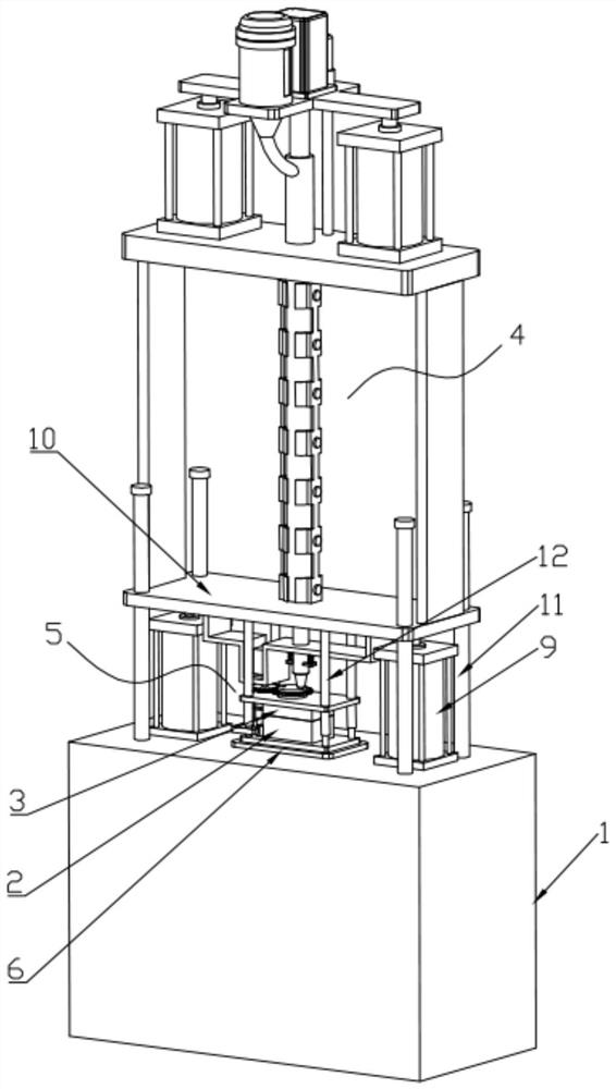
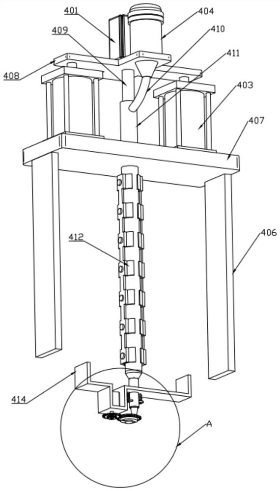
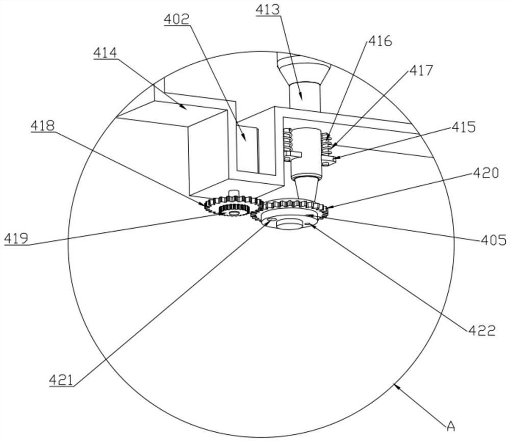
[0026] Such as Figure 1 to Figure 10 As shown, an injection molding device for a plastic pipe clamp includes a base 1, a lower injection mold 2, an upper injection mold 3, a filling mechanism 4 and a demoulding mechanism 5, and the lower injection mold 2 is fixed to the base through a fixing plate 6 1, the inside of the base 1 is equipped with a cylinder 7, the output end of the cylinder 7 is equipped with a thimble 8, and the upper end of the base 1 is fixed with two symmetrically arranged oil cylinders 9 on both sides of the fixed plate 6 , the output ends of the two oil cylinders one 9 are connected with a top plate 10, the top plate 10 is slidably arranged above the base 1 through several symmetrically arranged guide posts 11, and the lower e...


PUM


Abstract

The invention discloses an injection molding device for plastic pipe clips, relates to the technical field of injection molding equipment, and comprises a base, a lower injection mold, an upper injection mold, a filling mechanism and a demoulding mechanism. The invention realizes the change of the size of the gate by setting the filling mechanism, ensures that the flow state of the melt glue in the front and rear injection molding processes of the transition section remains consistent, and avoids the occurrence of flow marks; the injection molding process in which the gate size changes from small to large, flows through The melt in the runner will not maintain a high impact pressure all the time, which not only ensures the quality of the injection molding product, but also makes the mold have a longer service life, and can get rid of the air bubbles accumulated on the inner wall of the heating barrel to prevent Air enters the cavity and causes cavities inside or on the surface of the injection molded product; by setting a demoulding mechanism that cooperates with the filling mechanism, the adhesion to the mold is reduced, making it easier to demould, and the injection molded product will not be deformed Even damage the purpose.

Description

technical field [0001] The invention relates to the technical field of injection molding equipment, in particular to an injection molding device for plastic pipe clamps. Background technique [0002] Compared with other types of injection molding equipment, vertical injection molding machines have a series of advantages such as low center of gravity, small footprint, easy loading and unloading by manipulators, and easy implementation of insert molding. Therefore, some small-sized injection molding products are often used for injection molding. [0003] Our company has used this type of injection molding machine to inject plastic pipe clips for a long time, and found that the existing injection molding device still has the following disadvantages: 1. The size of the gate should be designed according to the situation of the product. It cannot be changed, but during the injection molding process, when the plastic pipe clamp is filled into the internal thread, the melt will dive...

Claims


Application Information

Patent Timeline
Patent Type & Authority Patents(China)
IPC IPC(8): B29C45/03B29C45/18B29C45/27B29C45/40B29C45/47B29C45/58B29C45/73B29C45/74B29C45/26
CPCB29C45/03B29C45/18B29C45/26B29C45/27B29C45/4005B29C45/47B29C45/58B29C45/73B29C45/74
Inventor 不公告发明人
Owner 芜湖富田电子科技有限公司
Why Eureka
Try Eureka