
An automatic liquid-shielding plastic glass and its spray coating method

A technology of plastic glass and automatic blocking, which is applied in the direction of chemical instruments and methods, coatings, synthetic resin layered products, etc. It can solve the problems that are not conducive to ensuring product quality and the appearance of flow marks on the transparent layer, so as to avoid the retention of coating liquid , Guarantee surface quality and prevent flow marks

Active Publication Date: 2020-04-17
SHENTONG TECH GRP CO LTD
View PDF3 Cites 0 Cited by
  • Summary
  • Abstract
  • Description
  • Claims
  • Application Information

AI Technical Summary

Problems solved by technology

When performing front-side flow coating, part of the flow coating liquid will flow to the back appearance surface, and appearance flow marks will appear on the transparent layer after heat curing, which is not conducive to ensuring product quality

Method used


Image

  • An automatic liquid-shielding plastic glass and its spray coating method
  • An automatic liquid-shielding plastic glass and its spray coating method
  • An automatic liquid-shielding plastic glass and its spray coating method

Examples


Embodiment 1

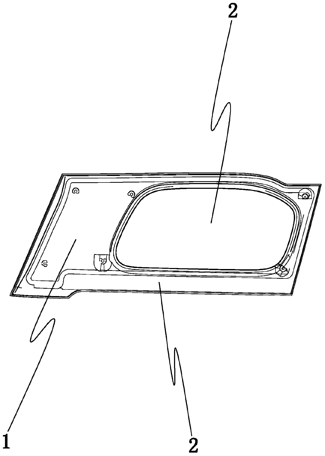
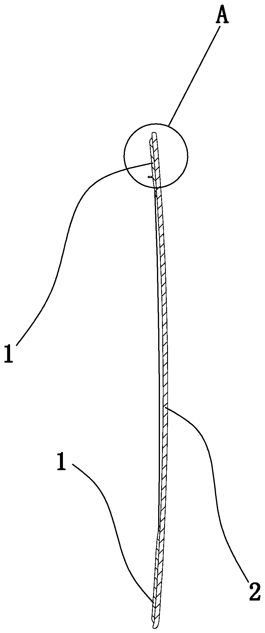
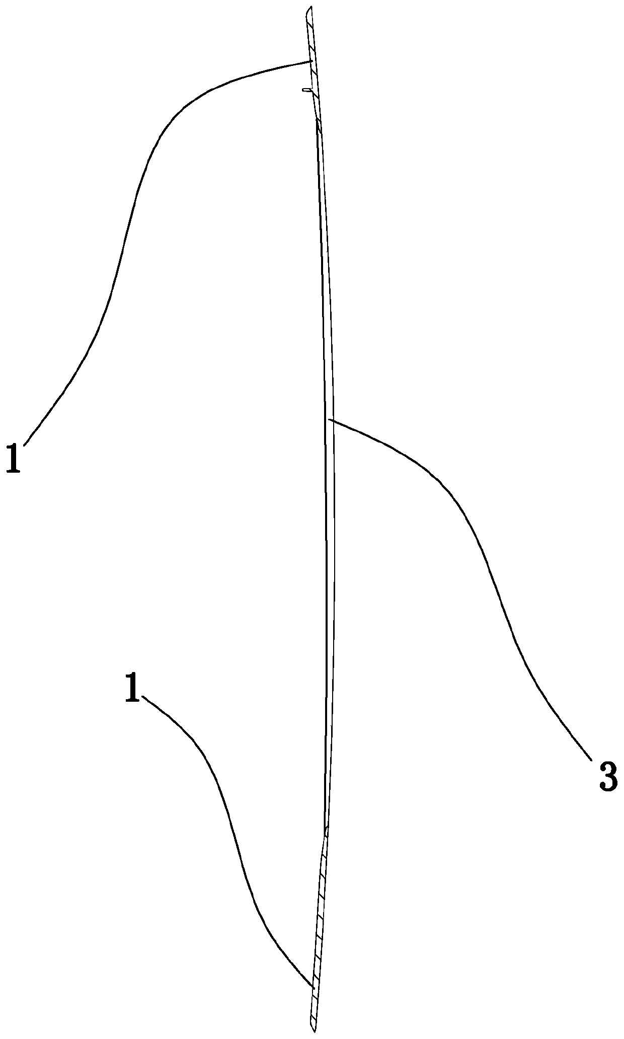
[0028] Such as Figure 1 to Figure 6 As shown, an automatic liquid-shielding plastic glass, including

[0029] A black border layer 1 and a transparent layer 2, the black border layer is connected to the transparent layer;

[0030] The black edge layer is provided with a curtain coating rib 3, and the black edge layer is between the curtain coating rib and the transparent layer;

[0031] The black border layer is provided with a through hole 4, one end of the through hole is the outer opening end, the other end of the through hole is the inner opening end, and the transparent layer seals the inner opening end.

[0032] When performing front-side flow coating, when part of the spray liquid flows to the back, it will flow down along the back. Due to the existence of the flow-coating ribs, the shower liquid will be blocked by the flow-coating ribs and fall directly without reaching the back. Appearance surface (appearance surface on the back of the transparent layer), which can...

Embodiment 2

[0039] On the basis of Example 1, such as Figure 7 As shown in , the black edge layer includes a body plate 2a and an outer ring plate 2b, the outer ring plate is provided with an inner hole, the body plate is located in the inner hole, the through hole is arranged on the body plate, the outer ring plate and The body boards are clamped, and the body board is connected with the transparent layer. The outer ring plate and the body plate are connected by a snap-in structure, and the snap-in structure includes a number of elastic protrusions 5 arranged on the wall of the inner hole and a number of snap holes arranged on the outer edge of the body plate. The protrusions correspond to the clamping holes one by one, and the elastic protrusions are clamped in the corresponding clamping holes.

[0040] During flow coating, quality problems are most likely to occur near the junction of the outer edge of the black edge layer and the transparent layer, and the outer edge of the black ed...


PUM


Abstract

The invention discloses an automatic liquid-blocking type plastic glass, which comprises a black edge layer and a transparent layer. The black edge layer is connected to the transparent layer. The black edge layer is provided with a curtain-coating baffling rib. The black edge layer is arranged between the curtain-coating baffling rib and the transparent layer. The black edge layer is provided with a through hole. One end of the through hole is an external opening end, the other end of the through hole is an internal opening end, and the transparent layer seals the internal opening end. The structure is reasonable; during the process of front curtain-coating, the curtain-coating liquid is prevented from flowing to the back surface, the flowing mark on the appearance after thermosetting isavoided, the surface quality of the transparent layer is guaranteed; the curtain coating liquid will not stay on the interface between the external edge of the black edge layer and the transparent layer, thus the moulding effect is ensured, and the performance and appearance are both qualified.

Description

technical field [0001] The invention belongs to the technical field of all-plastic glass, and in particular relates to an automatic liquid-blocking plastic glass and a flow coating method. Background technique [0002] All-plastic glass (plastic glass) has been widely used in the automotive field. All-plastic glass has the characteristics of good transparency, good chemical stability, excellent mechanical properties and good weather resistance. The all-plastic glass used in the automotive field mainly includes two parts: a transparent layer and a black edge layer. The black edge layer is set on the opposite side of the transparent layer. The transparent layer realizes the functions of light transmission and isolation, and the black edge layer is used as a skeleton. To increase the overall strength, the coverage area of ​​the black border layer is smaller than that of the transparent layer. In the production process of all-plastic glass, flow coating is required. Flow coatin...

Claims


Application Information

Patent Timeline
Patent Type & Authority Patents(China)
IPC IPC(8): B32B27/08B32B27/30B32B27/36B32B38/00
CPCB32B27/08B32B27/302B32B27/365B32B38/00B32B2250/24B32B2255/10B32B2307/41B32B2307/412B32B2605/08
Inventor 方立锋周宝聪饶聪超高左左
Owner SHENTONG TECH GRP CO LTD
Learn More