
A casting molding sand surface automatic spraying system and molding sand surface spraying process

An automatic spraying and casting technology, applied in the direction of the spraying device, etc., can solve the problems that the surface of the molding sand cannot be compacted twice, the nozzle cannot be rotated and tilted, and the paint cannot be covered in all directions, so as to facilitate cleaning and collection of residual paint, covering Wide range of effects

Active Publication Date: 2019-09-24
安徽合鑫机械设备制造有限公司
View PDF5 Cites 0 Cited by
  • Summary
  • Abstract
  • Description
  • Claims
  • Application Information

AI Technical Summary

Problems solved by technology

[0004] In order to solve the above problems, the present invention provides an automatic spraying system on the surface of casting molding sand and a spraying process on the surface of molding sand, which can solve the problem that the existing spraying machine cannot prevent the flow marks and accumulation of the paint, the nozzle cannot be rotated and tilted, and the paint cannot be covered in all directions. On the surface of the sand mold, the angle of spraying cannot be adjusted at will, and the surface of the molding sand cannot be compacted twice; it can realize the function of automatically spraying the casting coating on the surface of the molding sand, which can prevent the flow marks and accumulation of the coating, and the nozzle can be rotated and rotated. Inclined, the coating can cover the surface of the sand mold in all directions, the angle of spraying can be adjusted at will, and the surface of the molding sand can be compacted twice, etc.

Method used


Image

  • A casting molding sand surface automatic spraying system and molding sand surface spraying process
  • A casting molding sand surface automatic spraying system and molding sand surface spraying process
  • A casting molding sand surface automatic spraying system and molding sand surface spraying process

Examples


Embodiment Construction

[0026] In order to make the technical means, creative features, goals and effects achieved by the present invention easy to understand, the present invention will be further described below in conjunction with specific illustrations. It should be noted that, in the case of no conflict, the embodiments in the present application and the features in the embodiments can be combined with each other.

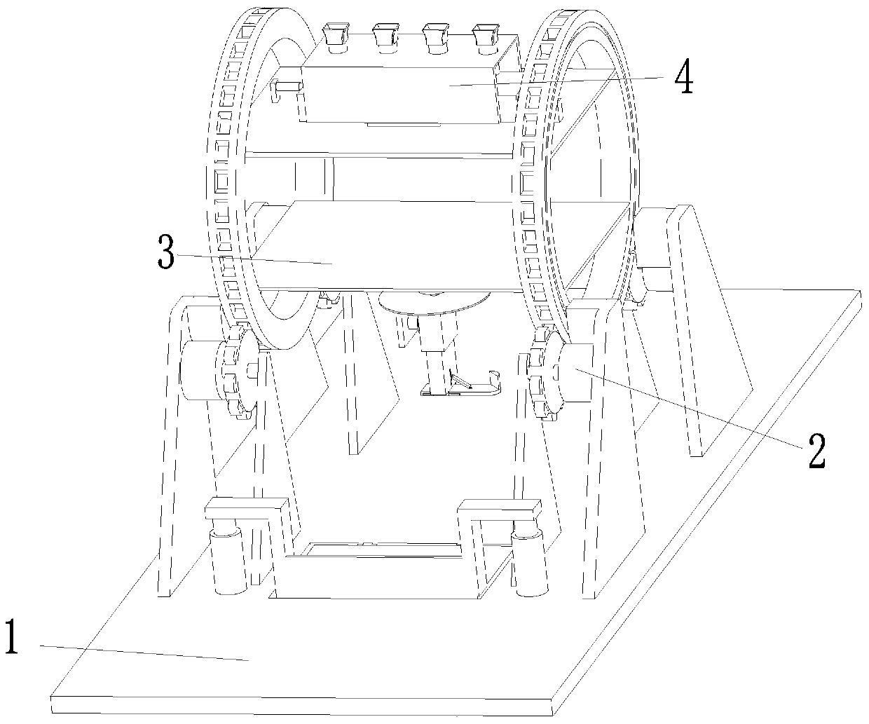
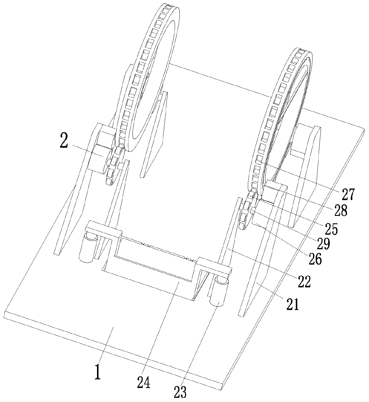
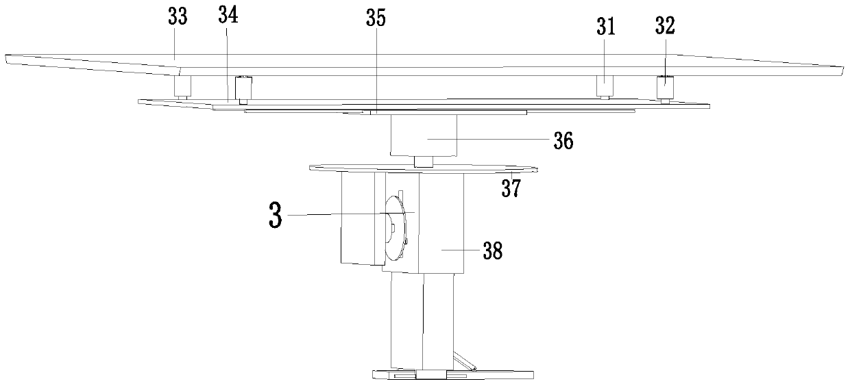
[0027] like Figure 1 to Figure 6 As shown, an automatic spraying system for the surface of foundry sand includes a bottom plate 1, a tumbling device 2, a compacting device 3, and a coating device 4. The middle part of the front end of the bottom plate 1 is provided with a hole, and the tumbling device 2 is installed in the middle of the bottom plate 1. On the upper end face, the compacting device 3 is installed on the lower inner side of the tumbling device 2 , and the coating device 4 is installed on the upper inner side of the tumbling device 2 .

[0028] The rolling device 2 inc...


PUM


Abstract

The invention relates to an automatic cast molding sand surface spraying system. The automatic cast molding sand surface spraying system comprises a bottom plate, a rolling device, a compaction deviceand a coating device. A hole is formed in the middle portion of the front end of the bottom plate. The rolling device is arranged on the upper end face of the middle portion of the bottom plate. Thecompaction device is arranged on the inner side face of the lower end of the rolling device. The coating device is arranged on the inner side face of the upper end of the rolling device. The automaticcast molding sand surface spraying system can solve the problems that according to an existing spraying machine, flow marks and stacking of coatings cannot be prevented, a sprayer cannot rotate or incline, the coatings cannot comprehensively cover the surface of a sand mould, the spraying angle cannot be adjusted at will, and secondary compaction cannot be conducted on the surface of molding sand; and the function of automatic spraying of the casting coatings to the surface of the molding sand can be achieved.

Description

technical field [0001] The invention relates to the technical field of casting, in particular to an automatic spraying system for casting molding sand surface and a molding sand surface spraying process. Background technique [0002] Sand casting is the most popular and simplest type of casting and has been used for centuries. Sand casting is used to manufacture large parts such as gray cast iron, ductile iron, stainless steel and other types of steel. The main steps Including painting, moulding, core making, molding, melting and pouring, cleaning etc. According to statistics, in my country or in the world, 60-70% of the castings are produced with sand molds, and about 70% of them are produced with clay sand molds. The main reason is that sand casting has lower cost, simpler production process and shorter production cycle than other casting methods. [0003] In sand casting, after the pouring process is completed, in order to make the casting easy to separate from the mold...

Claims


Application Information

Patent Timeline
Patent Type & Authority Patents(China)
IPC IPC(8): B05B13/02B05B13/04B05B15/68
Inventor 管冰倩
Owner 安徽合鑫机械设备制造有限公司
Learn More