A kind of coke oven hydrogen utilization method and system

A coke oven and hydrogen technology, applied in the field of coal coke ovens, can solve the problems of reduced efficiency, waste of energy, high temperature of low temperature coke and graphite of waste gas, and achieve the effects of improving coke oven productivity, increasing waste heat recovery, and improving coking benefits.

Active Publication Date: 2021-06-29
葛霖
View PDF0 Cites 0 Cited by
  • Summary
  • Abstract
  • Description
  • Claims
  • Application Information

AI Technical Summary

Problems solved by technology

[0006] Obviously, coke oven gas containing 50-60% hydrogen is difficult to separate hydrogen after coking
Cause waste of hydrogen resources
[0007] In short, the distilled raw gas is coked in the carbonization chamber, riser pipe, and bridge pipe, which wastes raw gas resources, brings great hidden dangers to safe production, increases the labor intensity and difficulty of equipment maintenance during the production process, and reduces the cost of coke ovens. Productivity, the reason is the cracking of macromolecular raw coal gas. At the same time, the light processing of coal tar requires hydrogenation, and the hydrogen resources containing 50-60% in the gas cannot be used, so there are still many in the coke oven process. Technical difficulties and pain points:
[0008] 1. The cracking reaction of macromolecular coal tar will cause a large amount of deposited carbon to adhere to the top of the carbonization chamber, the riser and the bridge pipe, which will bring great hidden dangers to safe production and increase the labor intensity and difficulty of equipment maintenance during the production process;
[0009] 2. The temperature of the furnace top space should be difficult to control;
[0010] 3. The top of the carbonization chamber burns graphite to remove coke, which wastes energy, wastes resources, and reduces the productivity of the coke oven;
[0011] 4. The pyrolysis of macromolecular coal tar reduces the yield of tar and reduces the benefit;
[0012] 5. Raw coal gas low-temperature coke graphite has a high temperature, which wastes the energy consumption of subsequent ammonia water injection and wastes waste heat

Method used


Image

  • A kind of coke oven hydrogen utilization method and system
  • A kind of coke oven hydrogen utilization method and system
  • A kind of coke oven hydrogen utilization method and system

Examples


Embodiment 1

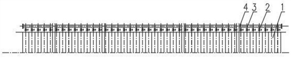
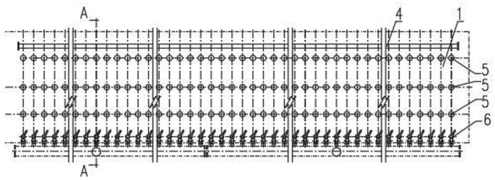
[0059] Such as figure 2 with 4 As shown, the coke oven hydrogen utilization system described in this embodiment is a system in which the duct 4 is arranged on the other side of the carbonization chamber riser 6; Pipe channel 4; the rising pipe 6 is provided with a flap valve 7; the other end of the coke oven carbonization chamber 1 on the side of the rising pipe 6 of the raw gas outlet is provided with a raw gas inlet and outlet, and the inlet and outlet are connected to the high temperature valve 2 , the high temperature valve 2 is externally connected to the raw gas pipe channel, the pipe channel 4 is arranged side by side parallel to the coke oven carbonization chamber 1, the pipe channel is connected to the high temperature valve 2 in a three-way type, and the high temperature valve 2 is connected to its corresponding coke oven carbonization chamber 1. A catalyst fixed bed 8 is provided in the conduit 4 and / or at the top of the carbonization chamber 1 and / or in the riser...

Embodiment 2

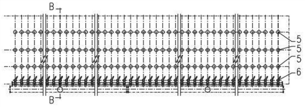
[0061] Such as image 3 with 5 As shown, the coke oven hydrogen utilization system described in this embodiment is a system in which the pipes and channels 4 are arranged on the same side of the carbonization chamber riser; The inlet and outlet, the inlet and outlet are connected to the inside of the high-temperature valve 2 through a three-way connection at the root of the outlet of the raw gas riser pipe assembly, and the outside of the high-temperature valve 2 is connected to the raw gas pipeline. A catalyst fixed bed 8 is arranged in the canal 4 and / or at the top of the carbonization chamber 1 and / or in the riser 6; the advantage of this embodiment is that it can well solve the technical transformation problem of the existing coke oven without changing the top carbonization of the coke oven. Chamber structure.

Embodiment 3

[0063] Such as figure 2 with 6 As shown, the pipe channel 4 is connected with the carbonization chamber 1 of the coke oven by using the existing furnace top carbonization chamber hole 5 to connect the connecting pipe 3, so that the connecting pipe 3 can be successfully solved for the technical transformation of the technical solution of the present invention for the existing coke oven, and its advantages It is not necessary to renovate the existing coke oven, and use the hole on the top of the carbonization chamber of the existing coke oven to connect the pipes and channels, and increase the length of the raw gas process, so as to increase the reaction time.

[0064] Further, when the coke oven carbonization chamber 1 is provided with a raw gas inlet and outlet at the other end of the raw gas outlet on the side of the rising pipe 6, the high-temperature valve 2 is connected to the corresponding coke oven carbonization chamber 1 through the furnace top carbonization chamber ho...


PUM


Abstract

The present invention relates to the field of coal coke ovens, in particular to a coke oven hydrogen utilization method and its system, especially suitable for the comprehensive utilization of hydrogen-rich raw gas in different coking stages of coke oven coking process. One or more carbonization chambers are sequentially introduced into another or several other carbonization chambers that have just been filled with coal through the raw gas pipeline system, so that hydrogen-rich raw gas can be introduced to form a hydrogen-rich environment in the carbonization chamber that has just been filled with coal, control, A method for adjusting and inducing the cracking reaction of raw coal gas, so that the cracking reaction can be transformed into a light-weight target product. The furnace top of the carbonization chamber of the present invention has high-temperature hydrogen with high activation energy, which can react with the hydrogenation reaction of graphite at the top of the carbonization chamber for secondary cracking of coal tar, and eliminate the burning process of opening the furnace cover 10 to 20 minutes in advance of the combustion and decoking process. Improve tar yield and coke oven productivity.

Description

technical field [0001] The invention relates to the field of coal coke ovens, in particular to a coke oven hydrogen utilization method and a system thereof, and is especially suitable for a technical method for the comprehensive utilization of hydrogen-rich raw gas in different coking stages of the coke oven coking process. Background technique [0002] In the coking process, the coking coal is heated and dry-distilled in the coke oven to generate coke, and at the same time, a large amount of raw coal gas is generated. The coke oven is usually composed of multiple carbonization chambers (hearths) in parallel, and each carbonization chamber is equipped with Coal inlet, raw gas outlet, rising pipe assembly and one-way flap valve. During the coking process of coal in the carbonization chamber, high-temperature raw gas of up to 850°C is produced. The raw gas enters the rising pipe assembly through the carbonization chamber raw gas outlet The ammonia water enters the air collecti...

Claims


Application Information

Patent Timeline
Patent Type & Authority Patents(China)
IPC IPC(8): C10B57/18
CPCC10B57/18
Inventor 葛霖葛京鹏葛亮
Owner 葛霖
Why Eureka
Try Eureka