Intelligent sentry box with moving function

A technology of intelligent sentry box and mobile function, which is applied in the direction of special buildings, instruments, small buildings, etc., can solve the problems of large limitations, inability to meet existing needs, and the inability to move the sentry box, so as to improve practicability and prolong service life , the effect of saving energy

Inactive Publication Date: 2020-09-29
杭州金镂智能科技有限公司
View PDF5 Cites 0 Cited by
  • Summary
  • Abstract
  • Description
  • Claims
  • Application Information

AI Technical Summary

Problems solved by technology

[0003] The existing sentry box cannot be moved, which has great limitations and cannot meet the existing needs

Method used


Image

  • Intelligent sentry box with moving function
  • Intelligent sentry box with moving function
  • Intelligent sentry box with moving function

Examples


Embodiment 1

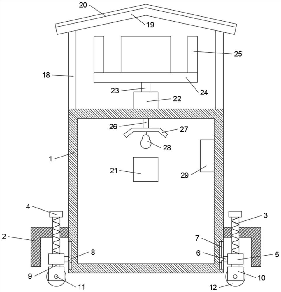
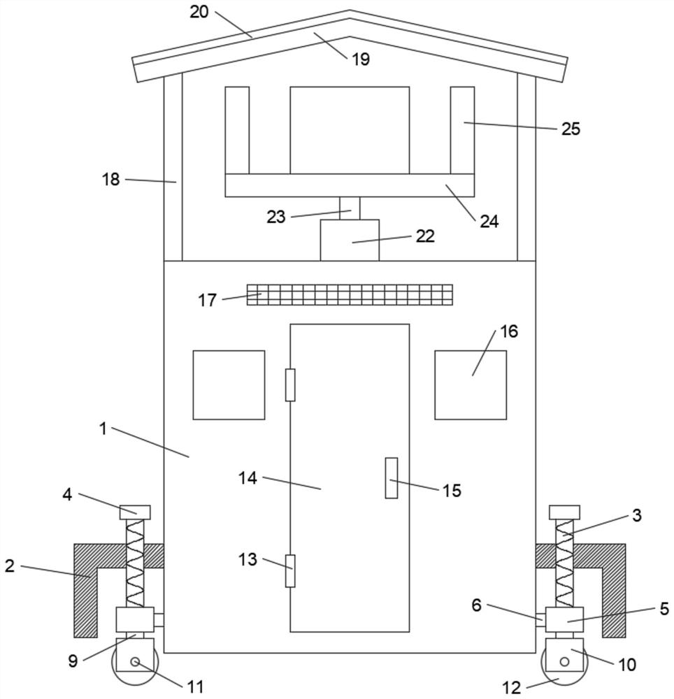
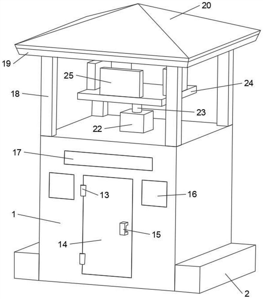
[0020] see Figure 1-3 , in an embodiment of the present invention, a smart sentry box with a mobile function includes a sentry box body 1, a protective shell 2 is arranged on the left and right sides of the sentry box body 1, a screw 3 is arranged on the upper end of the protective shell 2, and a screw 3 is fixedly connected to the top of the screw 3. Grip 4, the bottom end of screw rod 3 is connected with moving block 5 in rotation, connecting rod 6 is arranged on the side wall of moving block 5, and chute 7 is arranged on the left and right side walls of the sentry box body 1, and sliding groove 7 is installed in the chute 7. Block 8, slide block 8 is fixedly connected with connecting rod 6, and the lower end of described moving block 5 is provided with rotating shaft 9, and the lower end of rotating shaft 9 is rotatably connected with roller cover 10, and roller cover 10 is provided with roller shaft 11, and roller shaft 11 is rotatably connected with Roller 12, when the s...

Embodiment 2

[0027] In order to facilitate the control of the electrical appliances in the sentry box body 1, this embodiment is further improved on the basis of embodiment 1. The improvements are: a control box 29 is arranged in the sentry box body 1, and the control box 29 is connected to the battery 21, Motor 22, display screen 25 and illuminating lamp 28 are electrically connected, through control box 29, can control the electrical equipment in sentry box body 1, improve the practicability of this sentry box.

[0028] The working principle of the present embodiment is: in order to conveniently control the electrical appliances in the sentry box body 1, a control box 29 is arranged in the sentry box main body 1, and the control box 29 is connected with the storage battery 21, the motor 22, the display screen 25 and the lighting lamp respectively. 28 are electrically connected, and through the control box 29, the electrical equipment in the sentry box body 1 can be controlled to improve t...


PUM


Abstract

The invention discloses an intelligent sentry box with a moving function. The intelligent sentry box comprises a sentry box body, wherein protective shells are arranged on the left side and the rightside of the sentry box body correspondingly, screw rods are arranged at the upper ends of the protective shells correspondingly, grips are fixedly connected to the top ends of the screw rods correspondingly, moving blocks are rotationally connected to the bottom ends of the screw rods correspondingly, connecting rods are arranged on the side walls of the moving blocks correspondingly, sliding grooves are formed in the left side wall and the right side wall of the sentry box body correspondingly, sliding blocks are slidably installed in the sliding grooves and fixedly connected with the connecting rods correspondingly, rotating shafts are arranged at the lower ends of the moving blocks correspondingly, roller sleeves are rotationally connected to the lower ends of the rotating shafts correspondingly, rolling shafts are arranged in the roller sleeves correspondingly, and rollers are rotationally connected to the rolling shafts correspondingly. By arranging the rollers, when the sentry box body needs to be moved, the screw rods are rotated through the grips to drive the moving blocks to move downwards, then the rollers make contact with the ground and support the sentry box body, thesentry box body can be driven to move by rolling the rollers, after the sentry box body is moved to a proper position, the screw rods are rotated to enable the rollers to move upwards and move into the protective shells, and the lower end of the sentry box body makes contact with the ground.

Description

technical field [0001] The invention relates to the field of sentry boxes, in particular to an intelligent sentry box with a mobile function. Background technique [0002] The sentry box is a facility used to protect security personnel from the wind and rain. It is mostly found in various public places, such as busy streets, commercial streets, pedestrian streets, and various important traffic intersections. It is the same as the traffic sentry box for the public security department. The security point set up peacefully and outdoors is an important facility to assist civilian police and traffic police comrades in their work. [0003] The existing sentry box cannot be moved, has great limitations, and cannot meet the existing needs. Contents of the invention [0004] The purpose of the present invention is to provide an intelligent sentry box with a mobile function, so as to solve the problems raised in the above-mentioned background technology. [0005] To achieve the ab...

Claims


Application Information

Patent Timeline
Patent Type & Authority Applications(China)
IPC IPC(8): E04H1/12E04B1/343G09F9/00
CPCE04B1/34352E04H1/1205E04H1/1227G09F9/00
Inventor 蔡银云
Owner 杭州金镂智能科技有限公司
Why Eureka
Try Eureka