Eureka AIR delivers breakthrough ideas for toughest innovation challenges, trusted by R&D personnel around the world.

Orienting device for feet-lock bolt

A technology of directional device and locking foot bolt, which is applied in the installation of bolts, mining equipment, earthwork drilling and mining, etc. It can solve the problem of inability to remove the positioning cylinder, waste of workpieces, and the inability of the end of the L-shaped bolt to fit with the I-beam fit and other issues

Active Publication Date: 2020-09-29
贾承志 +2
View PDF18 Cites 1 Cited by
  • Summary
  • Abstract
  • Description
  • Claims
  • Application Information

AI Technical Summary

Problems solved by technology

However, there are still problems in the above-mentioned patents: the first meshing teeth are arranged on the steel arch frame, and the second meshing teeth are arranged on the L-shaped bolt. Therefore, the rod of the locking foot bolt must be inserted into the surrounding rock After the anchor hole is drilled, the combination of the first meshing tooth and the second meshing tooth can be realized, and the angle can be adjusted
The problem that still exists in the above patent is that it is not possible to adjust the angle during the insertion process
Although the above-mentioned patents provide that the inclination angle of the lock-foot anchor pipe can be adjusted during the construction process, there is a huge problem, that is, for the L-shaped anchor rod, after the anchor rod is introduced into the surrounding rock, the positioning cylinder cannot be positioned. remove from the anchor
In this way, it not only leads to the waste of the workpiece, but also due to the limitation of the positioning cylinder, the end of the L-shaped anchor rod cannot be fitted with the I-beam, which affects the welding of the anchor rod and the I-beam.

Method used


Image

  • Orienting device for feet-lock bolt
  • Orienting device for feet-lock bolt
  • Orienting device for feet-lock bolt

Examples


Embodiment Construction

[0023] The specific embodiments of the present invention will be described in further detail below in conjunction with the accompanying drawings, but the present invention is not limited to these embodiments, and any improvement or replacement in the basic spirit of this embodiment still belongs to the claims of the present invention. scope.

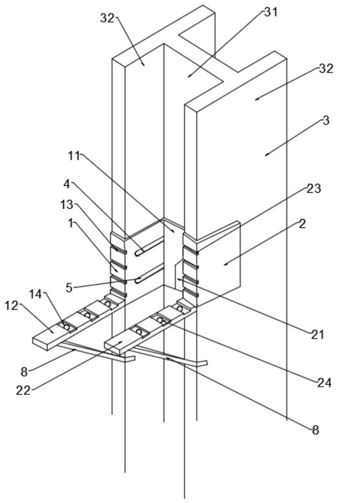
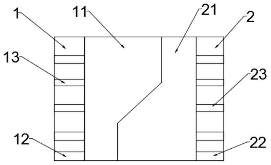
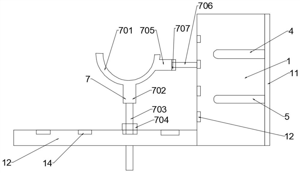
[0024] Example: such as Figure 1-4 As shown, the present embodiment provides an orientation device for L-shaped locking foot bolts.

[0025] Specifically, the locking pin anchor rod orientation device of this embodiment includes a first U-shaped splint 1, a second U-shaped splint 2 and an I-beam 3, and the end of the side wall of the first U-shaped splint has a laterally protruding The first butt plate 11 of the second U-shaped splint has a laterally protruding second butt plate 21 at the end of the side wall of the second U-shaped splint. The U-shaped grooves of the first U-shaped splint and the second U-shaped splint are clamped resp...


PUM


Abstract

The invention discloses an orienting device for a feet-lock bolt. The end of one side wall of a first U-shaped clamping plate and the end of one side wall of a second U-shaped clamping plate are respectively provided with an abutting plate that extends laterally, U-shaped grooves are arranged on wing plates at the left end and the right end of a web plate of H-shaped steel in a clamping manner respectively, the abutting plate of the first U-shaped clamping plate and the abutting plate of the second U-shaped clamping plate are attached to the web plate of the H-shaped steel respectively, and the opposite side walls of the first U-shaped clamping plate and the second U-shaped clamping plate are respectively provided with opposite upper through grooves and opposite lower through grooves. Theorienting device further comprises supporting frameworks, and the supporting frameworks are supported on the first U-shaped clamping plate and the second U-shaped clamping plate. A transverse caliperof the first U-shaped clamping plate and a transverse caliper of the second U-shaped clamping plate are respectively provided with a bracket assembly detachably clamped with clamping positions A, a clamping part detachably clamped with clamping positions B is arranged on one side of each bracket assembly, and each bracket assembly is also provided with an arc groove with an upward opening.

Description

technical field [0001] The invention relates to the technical field of tunnel construction, in particular to an orientation device for locking foot anchor rods. Background technique [0002] Disclosed in the Chinese patent CN109681250A is an installation structure of an L-shaped locking foot bolt, and specifically discloses: it includes a surrounding rock layer, a steel arch frame, and an L-shaped locking foot bolt; the L-shaped locking foot bolt includes a rod portion and The tail end portion perpendicular to the rod; also includes an adjuster, the adjuster includes a mounting plate, the mounting plate is fixedly connected with the side of the steel arch frame facing away from the surrounding rock layer, and the mounting plate is fixedly connected with a rotating Seat, the upper surface of the rotating seat is provided with a circle of first meshing teeth in the circumferential direction; the rotating seat is connected with a rotating seat, and the rotating seat is provided...

Claims


Application Information

Patent Timeline
Patent Type & Authority Applications(China)
IPC IPC(8): E21D21/00E21D20/00
CPCE21D20/00E21D21/0093
Inventor 贾承志王智杨仕星郑卢鑫刘小明陈海强李佳高振伟鲁世达刘用斌
Owner 贾承志
Why Eureka
Eureka Blog
Learn More