Inclined pushing device for feeding of rotary kiln

A technology of pushing device and rotary kiln, which is applied in the direction of rotary drum furnace, furnace, combustion type, etc., can solve the problems of incomplete feeding and material bonding.

Pending Publication Date: 2020-09-29
神彩科技股份有限公司
View PDF1 Cites 0 Cited by
  • Summary
  • Abstract
  • Description
  • Claims
  • Application Information

AI Technical Summary

Problems solved by technology

[0009] The technical problem to be solved by the present invention is to provide an inclined pushing device, which is suitable for the feeding method of continuous feeding of materials, and at the same time solves the problem that the materials are stuck and cannot be completely fed

Method used


Image

  • Inclined pushing device for feeding of rotary kiln

Examples


Embodiment Construction

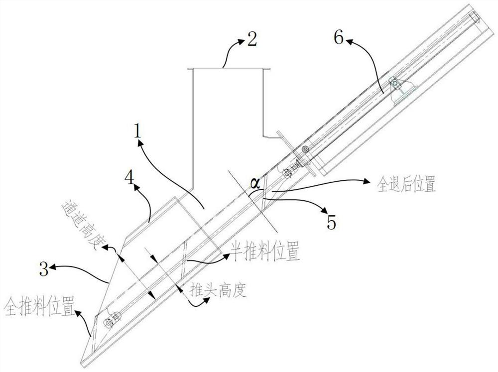
[0017] Such as figure 1 As shown, the rotary kiln feeding inclined pushing device includes an inclined pushing channel 1, in order to reduce the temperature of the inclined pushing channel 1, a water cooling chamber 4 is arranged outside the inclined pushing channel 1.

[0018] The top of the inclined pushing channel 1 is a feed port 2, the end of the inclined pushing channel 1 has a discharge port 3, and the inside of the inclined pushing channel 1 has a pushing head 5, and the pushing head 5 is driven by an oil cylinder 6 Moving from the head end of the inclined pushing channel 1 to the end, the material that enters the inclined pushing channel 1 at the inlet 2 is pushed to the outlet 3 . The oil cylinder 6 is arranged at the head end of the inclined pushing channel 1, and the piston rod of the oil cylinder 6 enters the inclined pushing channel 1 and is connected with the pushing head 5 and drives the pushing head, as figure 1 As shown, the push head 5 is driven by the oil ...


PUM


Abstract

The invention discloses an inclined pushing device for feeding of a rotary kiln. The inclined pushing device comprises an inclined pushing channel, wherein a feeding port is formed in the upper part of the inclined pushing channel, a discharging port is formed in the tail end of the inclined pushing channel, a push head is arranged in the inclined pushing channel and is driven by a power device tomove from the head end of the inclined pushing channel to the tail end, and a material entering the inclined pushing channel from the feeding port is pushed to the discharging port; in the inclined pushing channel, the push head is inclined, and is lower than the inclined pushing channel; the push head is lower than the inclined pushing channel, so that the channel has enough space to guarantee continuous feeding of most of the material; and due to the fact that the push head is lower than the inclined pushing channel, movement of the push head cannot affect a feeding process of the rotary kiln, that is, space above the push head can be used for continuously conveying the material all the time, the pushing act of the push head is not affected by the upstream material, continuous pushing can be performed, and the purpose of continuous feeding can be achieved.

Description

technical field [0001] The invention relates to a rotary kiln feeding inclined pushing device, which is used as a conveying part for conveying materials into the rotary kiln. Background technique [0002] In the rotary kiln system of hazardous waste incineration, the feeding of the rotary kiln has always been a relatively difficult problem to solve. The main difficulty is that the properties of the materials entering the rotary kiln are difficult to control. At present, most of the processes are all selected pushing device (as the authorized announcement number is a kind of rotary kiln feeding device disclosed by CN209689369U, a piston pusher is arranged in the feed tank, and the pushing piston head of the piston pusher is set Push the material in the feed tank in the feed tank body) or the gravity chute as the main equipment for feeding the rotary kiln, which solves the feeding problem of most materials. But there are also the following disadvantages: [0003] (1) The pus...

Claims


Application Information

Patent Timeline
Patent Type & Authority Applications(China)
IPC IPC(8): F23G5/20F23G5/44F27B7/32F27B7/38
CPCF23G5/20F23G5/444F27B7/3205F27B7/383
Inventor 周宗贤马圣平
Owner 神彩科技股份有限公司
Why Eureka
Try Eureka