
A rotary hearth furnace screw discharge device

A technology of spiral discharge and rotary hearth furnace, which is applied in the direction of furnaces, furnace types, hearth type furnaces, etc., can solve the problems of blade wear, rotary hearth furnace pellet breaking, pulverization, etc., to reduce the stress on blades and slow down The effect of blade wear speed and prolonging the service life of the machine

Active Publication Date: 2022-06-24
BAOSHAN IRON & STEEL CO LTD
View PDF0 Cites 0 Cited by
  • Summary
  • Abstract
  • Description
  • Claims
  • Application Information

AI Technical Summary

Problems solved by technology

The screw discharge machine is one of the main equipment of the rotary hearth furnace, which is used to discharge the high-temperature pellets on the furnace plate in a timely and efficient manner. Because the temperature of the metallized pellets to be processed is about 1000 ° C, the blades of the screw discharge machine are seriously worn , at the same time, the screw discharger is also easy to break and pulverize the rotary hearth furnace pellets

Method used


Image

  • A rotary hearth furnace screw discharge device
  • A rotary hearth furnace screw discharge device
  • A rotary hearth furnace screw discharge device

Examples


Embodiment Construction

[0023] Specific embodiments of the present invention will be described in detail below with reference to the accompanying drawings.

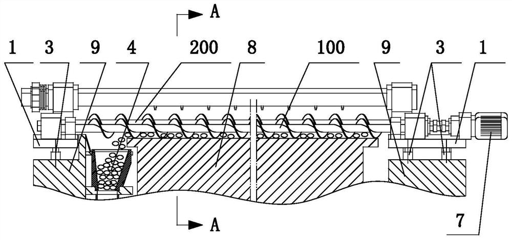
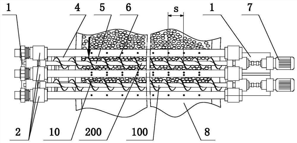
[0024] like Figures 1 to 4 As shown, the rotary hearth furnace screw discharging device according to an embodiment of the present invention includes a first screw discharging machine 100 arranged above the hearth 8 of the rotary hearth furnace, and also includes a first screw discharging machine 100 arranged on the first screw discharging machine 100. The second screw feeder 200 on the inlet side of the 2000 , the two ends of the first screw feeder 100 and the second screw feeder 200 are respectively arranged on the lifting platform 1 . The lifting platform 1 is lifted and lowered by the hydraulic cylinder 3 fixed on the system base 9 to compensate for the wear of the blades 6 of the first screw feeder 100 and the second screw feeder 200 . Preferably, each of the first screw feeder 100 and the second screw feeder 200 is driven by a separate mo...


PUM


Abstract

The invention discloses a rotary hearth furnace screw discharge device, which comprises a first screw discharge machine arranged above the hearth of the rotary hearth furnace, and also includes a first screw discharge machine arranged on the inlet side of the first screw discharge machine. Two screw discharge machines, the two ends of the first screw discharge machine and the second screw discharge machine are respectively arranged on the lifting platform; the mandrel of the second screw discharge machine is far from the hearth of the rotary hearth furnace The height is greater than the height of the mandrel of the first screw discharger from the hearth of the rotary hearth furnace; both sides of the first screw discharger and the second screw discharger are respectively provided with A blade cooling mechanism for cooling the blades of the first screw discharger and the second screw discharger. The spiral discharge device of the rotary hearth furnace of the present invention can greatly reduce the stress on the blades, slow down the wear speed of the blades, and prolong the on-machine service life of the spiral discharge device.

Description

technical field [0001] The invention relates to the technical field of rotary hearth furnaces, in particular to a spiral discharge device of the rotary hearth furnace. Background technique [0002] The dust sludge produced by the steel industry is 10% of steel production. Among the current three disposal methods, iron-making self-circulation is the main way, but Zn and alkali metals in the dust sludge cause damage to the blast furnace lining and nodules in the furnace, which affect the life and production indicators of the blast furnace. After entering the 1980s, with the increasing recognition of the importance of environmental protection and comprehensive utilization of resources, the research on dust and sludge treatment technology in iron and steel plants has also become a hot spot in the metallurgical field. Over the past 30 years, dozens of related technologies have been developed. Among them, the rotary hearth furnace treatment method has been widely recognized by ir...

Claims


Application Information

Patent Timeline
Patent Type & Authority Patents(China)
IPC IPC(8): F27D3/08C21B13/10
CPCF27D3/08C21B13/105
Inventor 肖永力王英杰关运泽李永谦
Owner BAOSHAN IRON & STEEL CO LTD
Features
  • Generate Ideas
  • Intellectual Property
  • Life Sciences
  • Materials
  • Tech Scout
  • Unparalleled Data Quality
  • Higher Quality Content
  • 60% Fewer Hallucinations
Learn More