Optical module debugging and testing system, optical module debugging and testing method and upper computer

An optical module and commissioning technology, which is applied in the field of optical communication, can solve problems such as low commissioning efficiency of optical modules, and achieve the effect of reducing commissioning costs and improving commissioning efficiency

Active Publication Date: 2020-09-29
STATE GRID INFORMATION & TELECOMM BRANCH
View PDF23 Cites 0 Cited by
  • Summary
  • Abstract
  • Description
  • Claims
  • Application Information

AI Technical Summary

Problems solved by technology

[0003] Optical modules need to be carried out in "three temperatures" during production and debugging. "Three temperatures" include normal temperature (such as 25°C), low temperature (such as -40°C) and high temperature (such as 85°C). Before commissioning, it takes a lot of time to adjust the temperature of the optical module to the standard temperature through the temperature control device, and a temperature control device can only adjust the temperature of one optical module, which makes the commissioning efficiency of the optical module low

Method used


Image

  • Optical module debugging and testing system, optical module debugging and testing method and upper computer
  • Optical module debugging and testing system, optical module debugging and testing method and upper computer
  • Optical module debugging and testing system, optical module debugging and testing method and upper computer

Examples


Embodiment Construction

[0038] The following will clearly and completely describe the technical solutions in the embodiments of the application with reference to the drawings in the embodiments of the application. Apparently, the described embodiments are only some of the embodiments of the application, not all of them. Based on the embodiments in this application, all other embodiments obtained by persons of ordinary skill in the art without making creative efforts belong to the scope of protection of this application.

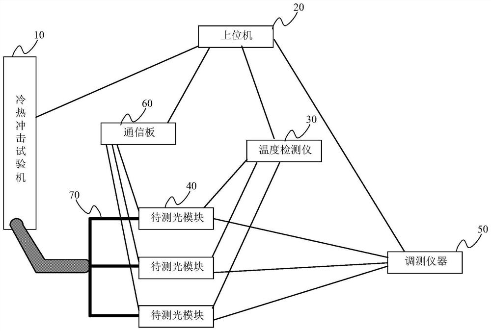
[0039] The embodiment of this application provides an optical module commissioning system, such as figure 1 As shown, it includes: thermal shock testing machine 10, host computer 20, multi-channel output module 70, temperature detector 30 and commissioning instrument 50; wherein,

[0040] The thermal shock testing machine 10 is used to spray gas at a standard temperature according to user instructions;

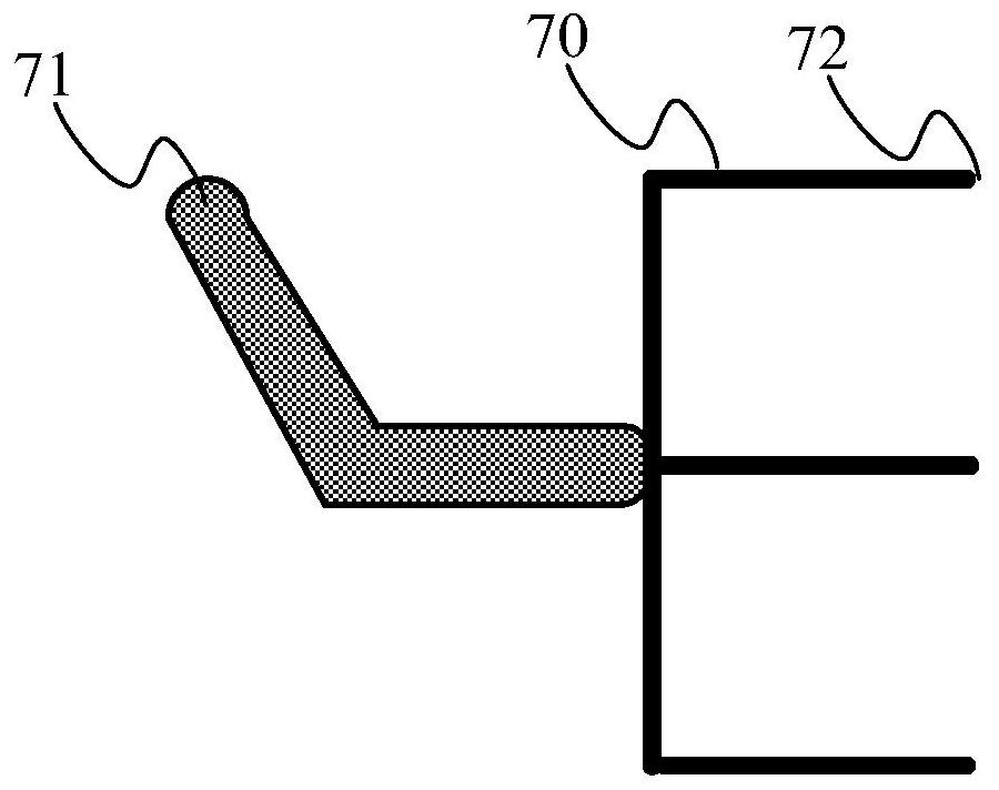
[0041] The multi-channel output module 70 is connected to the output end of th...


PUM


Abstract

The invention discloses an optical module debugging and testing system, an optical module debugging and testing method and an upper computer. According to the invention, the optical module debugging and testing system is used for carrying out temperature control on a to-be-tested optical module by spraying standard temperature gas through a cold and hot impact testing machine, and the standard temperature gas can be divided into multiple paths by a multi-path output module, so that the cold and hot impact testing machine is matched with the multi-path output module to carry out temperature control on a plurality of to-be-tested optical modules at the same time, the time for regulating and controlling the temperature of the to-be-tested optical module to be the standard temperature is shortened in a geometric multiple manner, and the debugging and testing efficiency of the to-be-tested optical modules can be improved; and one cold and hot impact testing machine can conduct temperature control over the multiple to-be-tested optical modules at the same time, and no expensive cold and hot impact testing machine needs to be additionally arranged while the debugging and testing efficiency is improved, so that the debugging and testing cost during debugging and testing of the to-be-tested optical modules can be reduced.

Description

technical field [0001] The present application relates to the technical field of optical communication, and more specifically, to an optical module commissioning system, an optical module commissioning method, and a host computer. Background technique [0002] The optical module (optical module) is composed of modules such as optoelectronic devices, functional circuits and optical interfaces. The optical module is mainly used to convert electrical signals into optical signals and send them through optical fibers, and receive optical signals returned by optical fibers, and convert the returned optical signals into Electrical signals and optical modules are important devices in the field of optical communications. [0003] Optical modules need to be carried out in "three temperatures" during production and debugging. "Three temperatures" include normal temperature (such as 25°C), low temperature (such as -40°C) and high temperature (such as 85°C). Before commissioning, it tak...

Claims


Application Information

Patent Timeline
Patent Type & Authority Applications(China)
IPC IPC(8): G05D23/19H04B10/073
CPCG05D23/1919H04B10/073
Inventor 吕俊峰李伯中陈芳樊秀娟李黎陈彦宇陈亮林楠林通夏晓文
Owner STATE GRID INFORMATION & TELECOMM BRANCH
Why Eureka
Try Eureka