Arc extinguishing device of dual-power switch

A dual power switch and arc extinguishing device technology, which is applied in the direction of electric switches, circuits, electrical components, etc., can solve the problems affecting product performance and service life, burning damage of dynamic and static contacts, poor arc extinguishing ability, etc. Achieve the effects of preventing arc channeling and arc pulling, improving breaking capacity and service life, and reducing internal temperature rise

Pending Publication Date: 2020-09-29
YUEQING DONGHAI ELECTRICAL APPLIANCE CO LTD
View PDF1 Cites 1 Cited by
  • Summary
  • Abstract
  • Description
  • Claims
  • Application Information

AI Technical Summary

Problems solved by technology

[0004] Therefore, the technical problem to be solved by the present invention is to overcome the short-circuit fault of the main power supply and the backup power supply caused by the simultaneous generation of arcs at both ends of the moving contact when the dual power switch in the prior art switches the main power supply and the backup power supply, and the extinguishing The arc ability is poor, and the generated arc and arc will cause burning damage to the dynamic and static contacts, which will affect the performance and service life of the product, so as to provide a method that can quickly extinguish the arc and effectively avoid the main power supply and backup power supply. The arc extinguishing device of the dual power switch that reduces the short-circuit fault caused by arc crossing and reduces the dynamic and static contacts being burned by the arc

Method used


Image

  • Arc extinguishing device of dual-power switch
  • Arc extinguishing device of dual-power switch
  • Arc extinguishing device of dual-power switch

Examples


Embodiment 1

[0040] Below in conjunction with accompanying drawing this embodiment is described in detail:

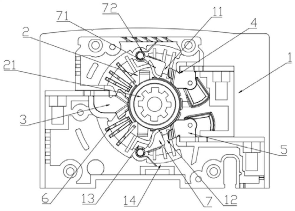
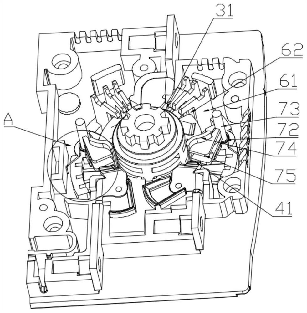
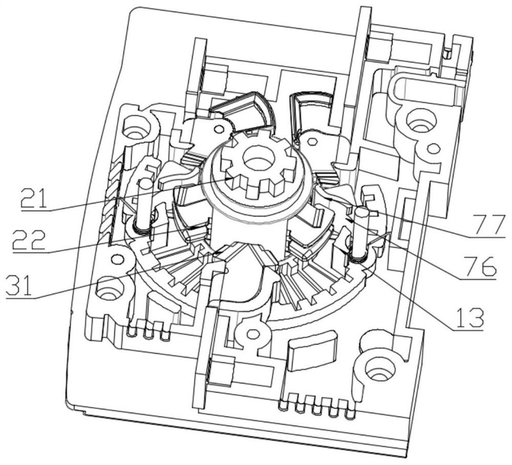
[0041] The present invention provides such Figure 1-4 The shown arc extinguishing device for a dual power switch includes a casing 1, a movable contact 2 rotatably arranged in the casing 1, and a moving contact 2 arranged in the casing 1 around the movable contact 2. The first static contact 3, the second static contact 4, and the third static contact 5. When the moving contact 2 is rotated under force, it has a The engaged main power state; and the standby power state engaged with the first static contact 3 and the third static contact 5, as well as the connection with the first static contact 3, the second In the power-off state where both the static contact 4 and the third static contact 5 are disconnected, the movable contact 2 switches back and forth between the "main power on state-power off state-backup power on state", Also includes:

[0042] The arc extinguishing plate ...


PUM


Abstract

The invention discloses an arc extinguishing device of a dual-power switch. Arc extinguishing separator plate structures are respectively and rotatably arranged on a joint path between a moving contact and a second static contact and a joint path between the moving contact and a third static contact. Electric arc and arc discharge caused by the separation of the moving contact and the static contact are cut off; when the moving contact passes through an arc extinguishing sheet assembly, the electric arc is quickly extinguished; therefore, when the moving contact is switched between the secondstatic contact and the third static contact in a rotating manner, a short-circuit accident caused by the fact that an electric arc is connected with the second static contact or the third static contact in a channeling manner is prevented. The technical scheme is adopted, an arc extinguishing separator plate structure is used to block and cut off an electric arc generated when the moving contact is disconnected with the second static contact or the third static contact. Arc channeling and arc discharge phenomena are prevented, the burning damage of the electric arc to moving and static contacts is reduced, the internal temperature rise of the dual-power switch is reduced, the arc extinguishing capability and arc extinguishing efficiency of the arc extinguishing device are greatly improved,the breaking capability of the dual-power switch is improved, and the service life of the dual-power switch is prolonged.

Description

technical field [0001] The invention relates to the technical field of low-voltage electrical appliances, in particular to an arc extinguishing device for a dual power supply switch. Background technique [0002] The contact structure of the dual power switch directly affects the temperature rise of the switch and the ability to make and break. When the contact structure breaks the circuit in the atmosphere, as long as the voltage exceeds 12-20V, the broken current exceeds 0.25-1A. An arc is usually generated in the head gap (also known as the arc gap) to keep the current connected until the arc is extinguished and the contact gap becomes an insulating medium. Copper ions remain. [0003] Chinese patent document CN203070945U discloses a contact device for a dual power switch, including a moving contact and a static contact, the static contact includes two contact pieces, the moving contact includes two moving contact pieces, two The moving contact piece forms a V shape, th...

Claims


Application Information

Patent Timeline
Patent Type & Authority Applications(China)
IPC IPC(8): H01H9/34H01H9/32H01H3/60
CPCH01H3/60H01H9/32H01H9/34
Inventor 南乐余
Owner YUEQING DONGHAI ELECTRICAL APPLIANCE CO LTD
Why Eureka
Try Eureka