Battery pack anti-collision reinforcing structure for new energy automobile
A new energy vehicle, anti-collision reinforcement technology, applied in battery pack parts, structural parts, circuits, etc., can solve the problem of new energy battery packs being easily damaged
- Summary
- Abstract
- Description
- Claims
- Application Information
AI Technical Summary
Problems solved by technology
Method used
Image

Examples
specific Embodiment 1
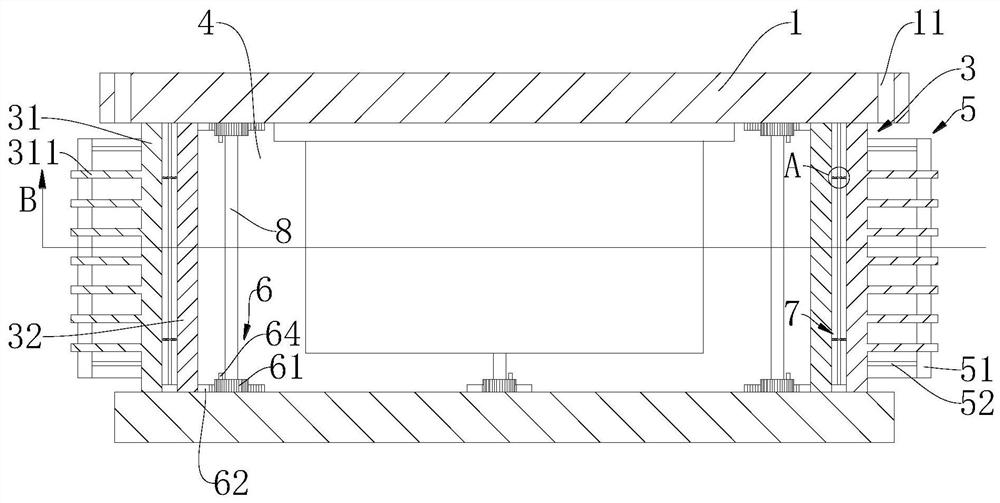
[0033] Such as Figure 1 to Figure 2 and Figure 5 As shown, a battery pack anti-collision reinforcement structure for a new energy vehicle provided by an embodiment of the present invention includes a flat plate 1, a first vertical plate 3, a second vertical plate 4 and a linkage device 6, wherein:
[0034] Two flat plates 1 are arranged parallel to each other, and the upper flat plate 1 is provided with a mounting hole 11 for mounting to the bottom of the vehicle, and two opposite first vertical plates 3 and two opposite second vertical plates 4 form a side plate ;
[0035] The first vertical plate 3 includes a first outer plate 31 and a first inner plate 32, the first outer plate 31 and the first inner plate 32 are arranged in parallel, and the upper end and the lower end of the first outer plate 31 are respectively slidably connected to the two flat plates 1. The upper end and the lower end of the first inner plate 32 are slidably connected to the two flat plates 1 respe...
specific Embodiment 2
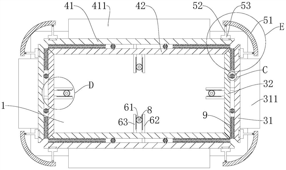
[0041] In Embodiment 1, since when the impact point is the junction of the first vertical plate 3 and the second vertical plate 4, and at the corner, the force on the first outer plate 31 or the second outer plate 41 is parallel to the plate surface, Then the linkage device 6 basically fails, and the first vertical plate 3 and the second vertical plate 4 are mainly bent and deformed, so it is still easy to cause damage to the internal battery pack. Therefore, on the basis of embodiment 2, as Figure 3 to Figure 4 As shown, the force component device 5 is also included in this embodiment. The force component device 5 includes a force-bearing piece 51 and a support member. The support member includes a force-bearing rod 52 and a connecting plate 53. The force-bearing rod 52 is fixedly connected to the connecting plate 53. The load-bearing piece 51 is arc-shaped, and both ends of the force-bearing piece 51 are provided with supports, and the two load-bearing rods 52 are respective...
specific Embodiment 3
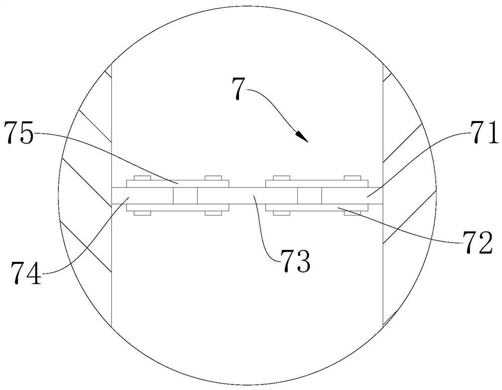
[0044] In Embodiment 1 or Embodiment 2, when a continuous force impact occurs, the energy absorption of the device is too limited, and because the pin shaft 64 is generally low in shear strength, it is easy to occur when a slight impact occurs. broken, so that the replacement of pin shaft 64 is too frequent and unreasonable, so on the basis of embodiment 1 or embodiment 2, as Figure 1 to Figure 5 As shown, in this embodiment, an energy absorbing device 7 and a rubber pad 9 are also included. The material of the pin shaft 64 is aluminum 1050A. The energy absorbing device 7 includes a first clamp 71, a first connecting rod 72, an energy absorbing sheet 73, a first Two clamping plates 74 and second connecting rods 75, one end of the two first connecting rods 72 are respectively hinged to the first clamping plate 71, the other end of one first connecting rod 72 is hinged to one end of the energy-absorbing sheet 73, and the other end The other end of a connecting rod 72 is hinged ...
PUM
 Abstract
Description
Claims
Application Information
 - R&D
- Intellectual Property
- Life Sciences
- Materials
- Tech Scout
- Unparalleled Data Quality
- Higher Quality Content
- 60% Fewer Hallucinations
Browse by: Latest US Patents, China's latest patents, Technical Efficacy Thesaurus, Application Domain, Technology Topic, Popular Technical Reports.
© 2025 PatSnap. All rights reserved.Legal|Privacy policy|Modern Slavery Act Transparency Statement|Sitemap|About US| Contact US: help@patsnap.com