Heating equipment capable of adjusting steam flow direction

A technology for heating equipment and steam, which is applied to cooking utensils, steam cooking utensils, household utensils, etc., can solve the problems of unfavorable surface heating of food to be grilled, limitation of activity range, etc., and achieve the effect of uniform effect and enhanced effect.

Pending Publication Date: 2020-10-02
NINGBO FOTILE KITCHEN WARE CO LTD
View PDF1 Cites 0 Cited by
  • Summary
  • Abstract
  • Description
  • Claims
  • Application Information

AI Technical Summary

Problems solved by technology

However, in the rotary electric oven of the invention, the position of the exhaust fan in the electric oven body is fixed, and the airflow direction blown out when the exhaust fan rotates is also fixed, which will cause hot air to be blown in the electric oven body The range of motion is limited, which is not conducive to the uniform heating of the surface of the food to be grilled

Method used


Image

  • Heating equipment capable of adjusting steam flow direction
  • Heating equipment capable of adjusting steam flow direction
  • Heating equipment capable of adjusting steam flow direction

Examples


Embodiment 1

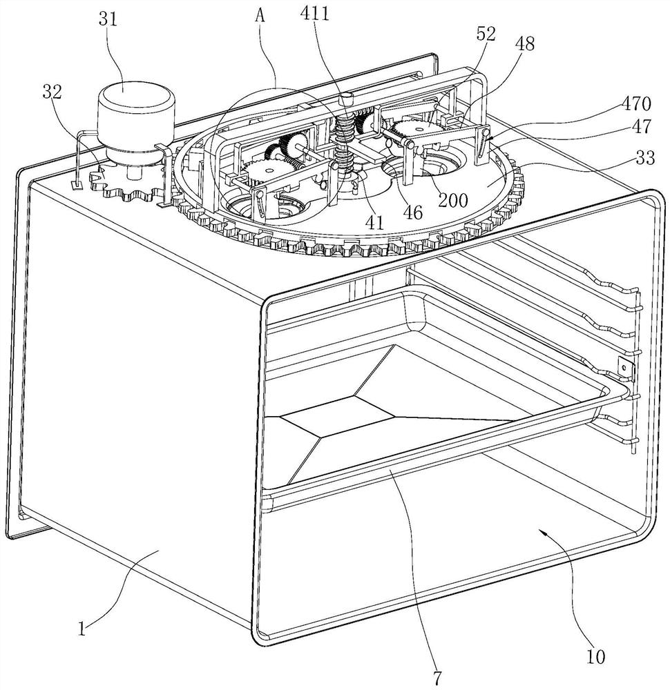
[0068] Such as Figure 1~3 As shown, this embodiment provides a heating device with adjustable steam flow direction, specifically a steam box with adjustable steam flow direction. The steamer includes:

[0069] The inner tank 1 is formed with a chamber 10, the top of the chamber 10 has an opening 100 formed around the central axis of the chamber 10, and the tray 7 for holding food is placed in the chamber 10; the structure of the inner tank 1 is shown in Figure 7 shown;

[0070] A steam generating device (not shown in the figure) generates steam entering the chamber 10; the steam generating device has a steam delivery pipe 5 for steam delivery to the inner bag chamber 10, and the outlet end of the steam delivery pipe 5 is located at Inside the inner tank chamber 10;

[0071] Two exhaust fans are respectively arranged on the left and right sides in the chamber 10. The exhaust fan has a rotating shaft 21 and a fan blade 22 rotating with the rotating shaft 21. The fan blade 2...

Embodiment 2

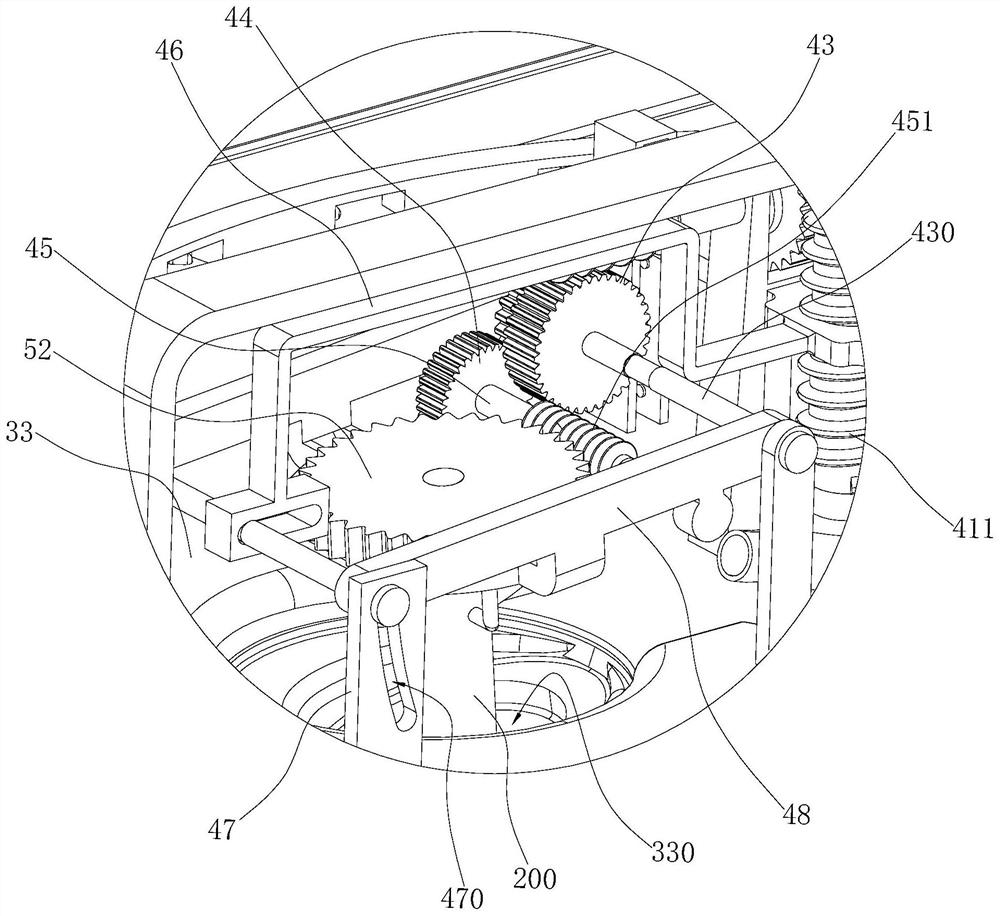
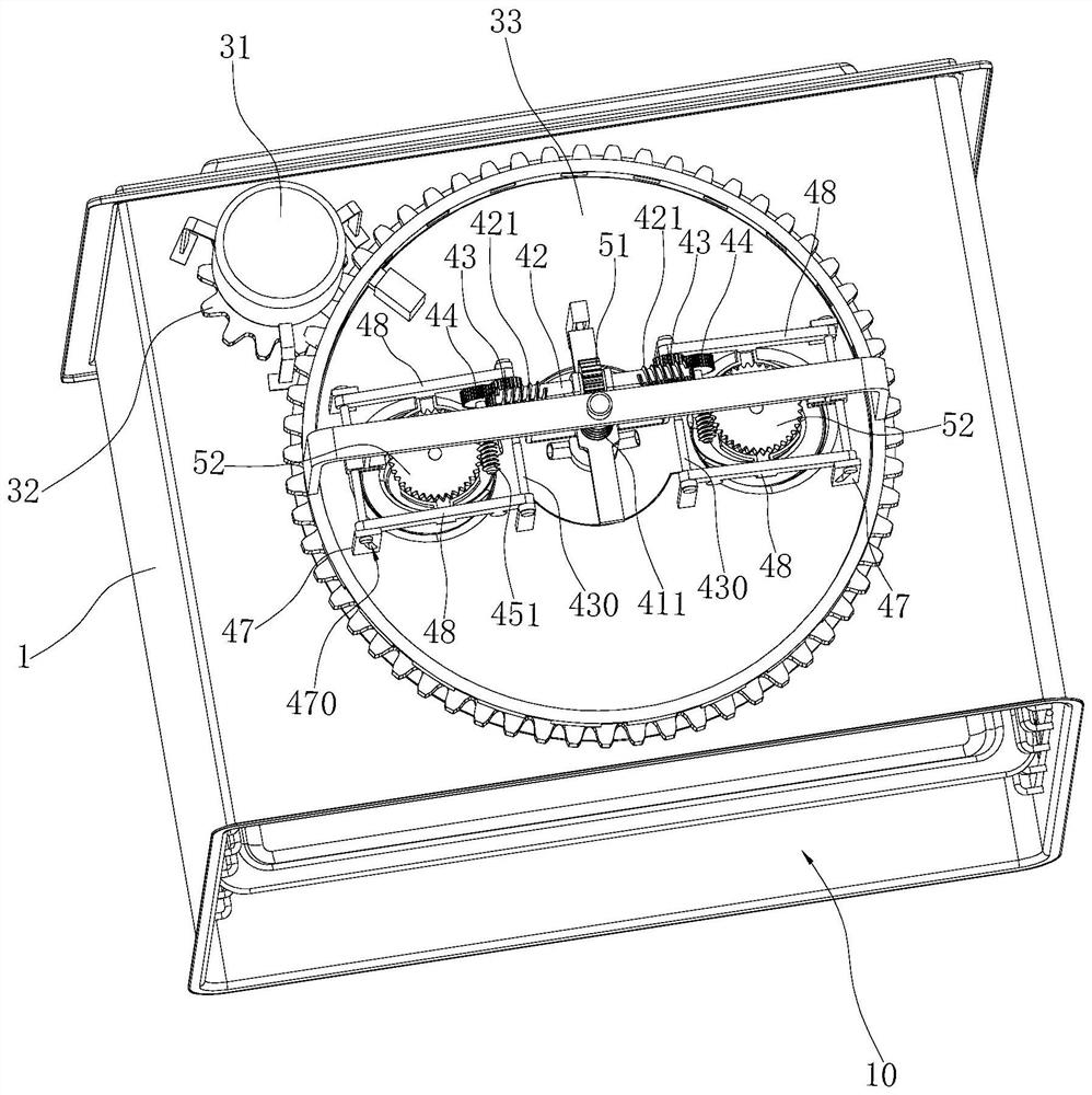
[0095] Such as Figure 8-11 As shown, the second embodiment provides another steam box that can adjust the direction of steam flow. The difference from the structure of the steam box in the first embodiment is that both the first driving mechanism and the second driving mechanism of the second embodiment are adjusted.

[0096] specifically;

[0097] The first drive mechanism includes:

[0098] The first motor 31' is arranged on the outside of the chamber 10 and is located on the top of the inner container 1;

[0099] The first driving gear 32' is connected with the transmission of the first motor 31';

[0100] The first driven gear 33' has a rotating hole 330' for the shaft 21 to pass through to enter the chamber 10, the first driven gear 33' is engaged with the first driving gear 32', and the first driven gear 33' is meshed with the first driving gear 32'. The opening 100 is adapted to make it move along the opening 100; wherein, the forming direction of the opening 100 i...


PUM


Abstract

The invention relates to heating equipment capable of adjusting a steam flow direction. The heating equipment comprises an inner container, a steam generating device and at least one exhaust fan; a cavity is formed in the inner container; the steam generating device generates steam entering the cavity of the inner container; the exhaust fan is provided with a fan with a rotating shaft and fan blades rotating along with the rotating shaft; and the fan blades are arranged in the cavity of the inner container. The heating equipment is characterized in that the exhaust fan can rotate in the axialdirection of the rotating shaft. When the fan blades of the exhaust fan rotate, the angle of the plane where the fan blades are located can be changed along with axial rotation of the fan rotating shaft of the exhaust fan along with the exhaust fan, airflow blown out of the rotating fan blades can be blown to the surface of food in multiple directions, and the effect of heating and steaming the surface of the food through hot steam is enhanced.

Description

technical field [0001] The invention relates to the field of steam heating equipment, in particular to a heating equipment capable of adjusting the flow direction of steam. Background technique [0002] In the current steam heating equipment market, the steam box is a kind of kitchen heating equipment that is popular among users. Users can use the steamer to steam all kinds of delicacies. [0003] The present steamer mainly includes an inner container and a steam generating device for discharging hot steam into the inner container, and the steam generating device usually adopts a steam generator or a heating plate. In a steam box using a steam generator as a steam generating device, a large amount of water is stored in the steam generator. After the steam generator starts heating, the water will form high-temperature steam, and then be discharged to the inner tank of the steam box. to heat food with high-temperature steam. In the steam box using the heating plate as the s...

Claims


Application Information

Patent Timeline
Patent Type & Authority Applications(China)
IPC IPC(8): A47J27/04A47J36/00
CPCA47J27/04A47J36/00A47J2027/043
Inventor 余浩曹骥王丁杨均
Owner NINGBO FOTILE KITCHEN WARE CO LTD
Why Eureka
Try Eureka