Aluminum profile cutting equipment

A technology for cutting equipment and aluminum profiles, which is used in metal processing equipment, clamping, and supporting. It can solve the problems of inconvenient cleaning of the surface of profiles and inconvenient clamping, and achieve the effects of fast clamping, reduced vibration and high efficiency.

Inactive Publication Date: 2020-10-02
李超
View PDF0 Cites 3 Cited by
  • Summary
  • Abstract
  • Description
  • Claims
  • Application Information

AI Technical Summary

Problems solved by technology

[0003] The existing profile cutting equipment is inconvenient to clamp and cannot clean the profile surface while cutting

Method used


Image

  • Aluminum profile cutting equipment
  • Aluminum profile cutting equipment
  • Aluminum profile cutting equipment

Examples


Embodiment 1

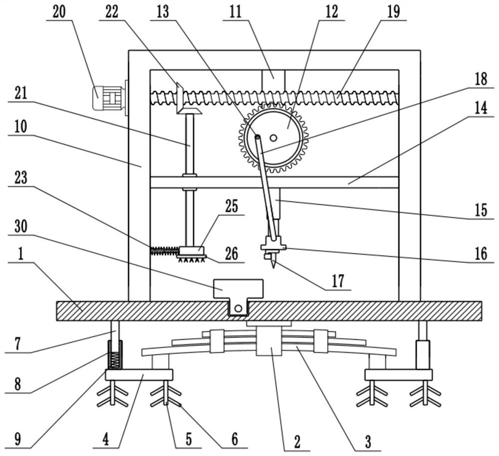
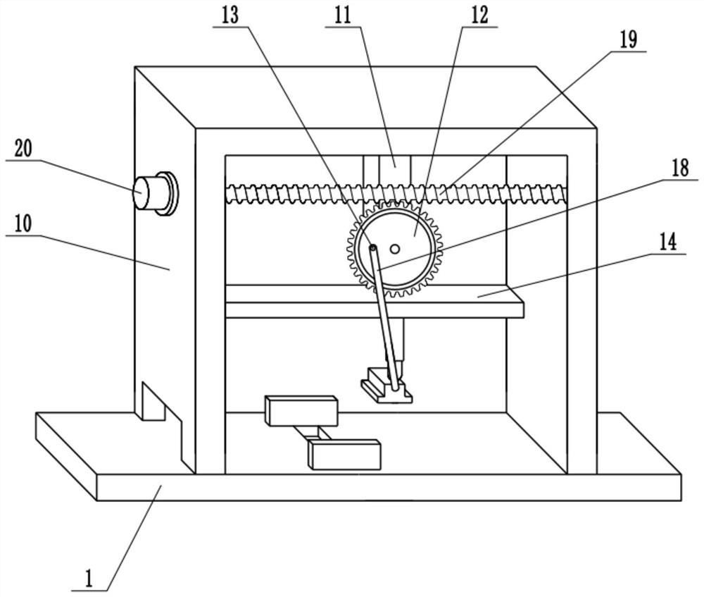
[0023] see Figure 1-4 , in an embodiment of the present invention, an aluminum profile cutting equipment includes a fixed table 1, a fixed frame 10, a mounting plate 14, a lifting seat 16 and a cutting machine 17, the upper surface of the fixed table 1 is fixedly connected with a fixed frame 10, and the fixed frame The top of 10 is fixedly connected with bracket 11, and the lower end of bracket 11 is connected with worm wheel 12 in rotation, and the surface of worm wheel 12 is fixedly connected with fixed rod 13 near the edge, and the bottom of worm wheel 12 is provided with mounting plate 14, and the two ends of mounting plate 14 and The inner wall of the fixed frame 10 is fixedly connected, the lower surface of the mounting plate 14 is fixedly connected with the first telescopic guide rod 15, the lower end of the first telescopic guide rod 15 is fixedly connected with the lifting seat 16, and the lower surface of the lifting seat 16 is equipped with a cutting machine 17 , t...

Embodiment 2

[0025] On the basis of Embodiment 1, a shock absorbing mechanism is installed on the bottom of the fixed table 1, and the shock absorbing mechanism includes a mounting bracket 2, a leaf spring 3, a support plate 4, a support rod 7, a sleeve 8 and a shock absorbing spring 9, and the fixed table The bottom of 1 is fixedly connected with a mounting frame 2, a leaf spring 3 is installed on the mounting frame 2, a supporting plate 4 is installed at the end of the leaf spring 3, the supporting plate 4 is connected to the ground, and the lower surface of the supporting plate 4 is fixedly connected with Fixed pile 5, fixed rod 6 is distributed on the fixed pile 5, fixed pile 5, fixed rod 6 are embedded in the ground, utilize fixed pile 5, fixed rod 6 to improve the stability of this device, utilize plate spring 3 to play the function of shock absorption Function, the lower surface of the fixed table 1 is fixedly connected with a support rod 7, the lower end of the support rod 7 is prov...


PUM


Abstract

The invention relates to the field of machining equipment, in particular to aluminum profile cutting equipment. The aluminum profile cutting equipment comprises a fixing table, a fixing frame, a mounting plate, a lifting seat and a cutting machine, the fixing frame is fixedly connected to the upper surface of the fixing table, a support is fixedly connected to the top of the fixing frame, a worm gear is rotationally connected to the lower end of the support, the mounting plate is arranged below the worm gear, a first telescopic guide rod is fixedly connected to the lower surface of the mounting plate, a lifting seat is fixedly connected to the lower end of the first telescopic guide rod, a worm is arranged above the worm gear, a second telescopic guide rod is fixedly connected to the innerside wall of the fixing frame, a movable frame is fixedly connected to the end of the second telescopic guide rod, and a brush plate is mounted on the lower surface of the movable frame. A bidirectional lead screw is used for driving a clamping plate to clamp the aluminum profile, so that the aluminum profile is kept stable, the clamping speed is high, the efficiency is high, the brush plate is driven to move left and right while cutting operation is carried out, the brush plate is used for cleaning the surface of the aluminum profile, and impurities on the surface are removed.

Description

technical field [0001] The invention relates to the field of machining equipment, more specifically, an aluminum profile cutting equipment. Background technique [0002] The content of aluminum in the earth's crust is second only to oxygen and silicon, ranking third, and is the most abundant metal element in the earth's crust. The development of the three important industries of aviation, construction and automobile requires the material properties to have the unique properties of aluminum and its alloys. Aluminum profiles are widely used in daily production and life. [0003] The existing profile cutting equipment is inconvenient for clamping, and cannot clean the profile surface while cutting. Contents of the invention [0004] The purpose of the present invention is to provide an aluminum profile cutting equipment to solve the problems raised in the above background technology. [0005] To achieve the above object, the present invention provides the following technica...

Claims


Application Information

Patent Timeline
Patent Type & Authority Applications(China)
IPC IPC(8): B23D79/00B23Q3/06B23Q5/34B23Q11/00B23Q5/40
CPCB23D79/00B23Q3/06B23Q5/34B23Q5/40B23Q11/0032B23Q11/0042
Inventor 李超
Owner 李超
Why Eureka
Try Eureka