Elevator guide rail connecting structure and elevator

A connecting structure and elevator guide rail technology, which is applied in the field of elevators, can solve the problems of increasing rectangular connecting plates, consuming materials, increasing the configuration space of guide rail connections, etc., and achieves the effects of economical connection, saving plates, and reducing the thickness of plates

Pending Publication Date: 2020-10-02
SHANGHAI MITSUBISHI ELEVATOR CO LTD
View PDF0 Cites 0 Cited by
  • Summary
  • Abstract
  • Description
  • Claims
  • Application Information

AI Technical Summary

Problems solved by technology

Increasing the thickness of the rectangular connecting plate will consume more materials on the one hand, and on the other hand, after thickening the connecting plate, longer connecting bolts will be used, which will increase the space for the connecting configuration of the guide rail, which may affect the layout of the elevator

Method used


Image

  • Elevator guide rail connecting structure and elevator
  • Elevator guide rail connecting structure and elevator
  • Elevator guide rail connecting structure and elevator

Examples


Embodiment 1

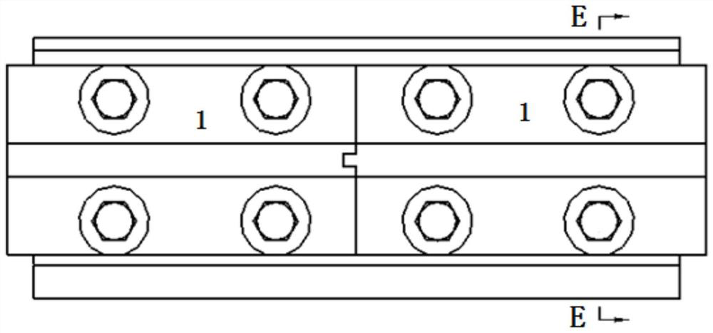
[0057] Such as Figure 1 to Figure 10 As shown, the elevator guide rail connection structure includes a guide rail 1 and a connecting plate 2;

[0058]The bottom surface of the guide rail 1 is T-shaped perpendicular to the guide surface;

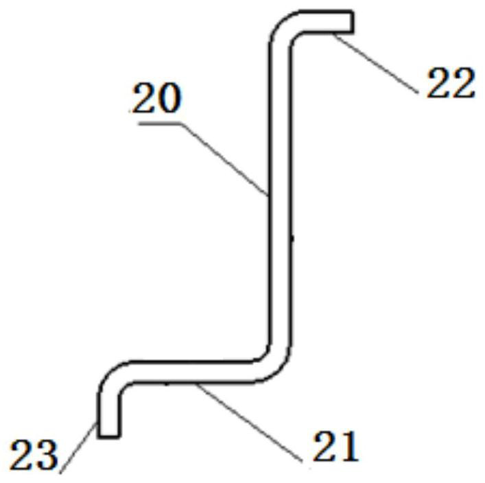
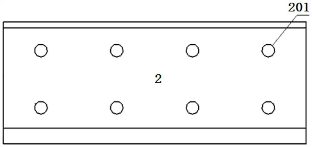
[0059] The connecting plate 2 is integrally formed, including a rectangular support portion 20 and a main reinforcing portion 21;

[0060] The main reinforcing part 21 is bent backward from the first end of the supporting part 20, and the first end is the left end or the right end;

[0061] The support portion 20 is vertically provided with a plurality of through holes 201;

[0062] Fasten the supporting part 20 of the connecting plate 2 with the bottom surfaces of the two docking rails 1 by bolts passing through the through holes 201 of the supporting parts 20 and the holes on the bottom surfaces of the two docking rails 1;

[0063] The front side of the support part 20 is attached to the bottom surface of the guide rail 1;

[0064] The...

Embodiment 2

[0068] Based on the connecting structure of elevator guide rails in Embodiment 1, the main reinforcing part 21 is rectangular, and the ratio of the length of the bolt at the rear side of the bottom surface of the guide rail 1 to the front and rear length of the main reinforcing part 21 is 0.5-1.1.

[0069] The elevator guide rail connection structure of the second embodiment is beneficial to reduce the occupied space of the elevator guide rail connection structure.

Embodiment 3

[0071] Based on the elevator guide rail connection structure of embodiment two, such as figure 1 , Figure 4 As shown, the connecting plate 2 also includes a main extension 23;

[0072] The main extension part 23 is parallel to the support part 20;

[0073] The main extension part 23 is bent from the rear end of the main reinforcing part 21 to the side away from the through hole.

[0074] Preferably, the main reinforcement part 21 is bent backwards from the first end of the support part 20 to form a 90° 0 ;

[0075] The main extension part 23 is bent at 90 degrees from the rear end of the main reinforcing part 21 to the side away from the through hole. 0 .

[0076] In the elevator guide rail connection structure of the third embodiment, the main extension part 23 of the connecting plate 2 is bent away from the surface of the main reinforcing part 21 and extends in a direction away from the through hole. The bending and forming of the main extension part 23 increases the ...


PUM


Abstract

The invention discloses an elevator guide rail connecting structure. The elevator guide rail connecting structure is characterized in that the bottom surfaces of guide rails are perpendicular to guidesurfaces to form a T shape; a connecting plate comprises a rectangular supporting part and a main reinforcing part; the main reinforcing part is bent backwards from the first end of the supporting part, the first end is the left end or the right end, and a plurality of through holes are formed in the supporting part in the vertical direction; bolts penetrate through the through holes of the supporting part and holes in the bottom faces of two butt joint guide rails to fasten the supporting part of the connecting plate and the bottom faces of the two butt joint guide rails together; and the front side of the supporting part is attached to the bottom faces of the guide rails, and the main reinforcing part extends forwards and can intersect with the bottom faces of the guide rails. The invention further discloses an elevator using the elevator guide rail connecting structure. According to the elevator guide rail connecting structure, the thickness of a connecting plate can be reduced while the space is not occupied and front-back stress transmitted by the guide surfaces of the guide rails is effectively borne, the plate is saved, and connection between the elevator guide rails can bebetter and more economically achieved.

Description

technical field [0001] The invention relates to elevator technology, in particular to an elevator guide rail connection structure and an elevator. Background technique [0002] The moving unit in the elevator (such as the elevator car and the counterweight) moves in a specified direction through the guidance of one or more guide rail lines. The moving elevator unit also often includes a braking device which, in an emergency, catches the guide rails in the guide rail line to bring the moving elevator unit to a stop. Each guide rail line includes a plurality of guide rails arranged continuously, and these guide rails are connected together to form a guide rail line. [0003] In the prior art, continuous guide rails are connected to each other by connecting plates, and the connecting plates are fixed to the bottom of the continuous guide rails (we take the side where the guide surface is located on the section of the guide rail as the top and the other side as the bottom). Th...

Claims


Application Information

Patent Timeline
Patent Type & Authority Applications(China)
IPC IPC(8): B66B7/02
CPCB66B7/023B66B7/026
Inventor 蒋勇高腾
Owner SHANGHAI MITSUBISHI ELEVATOR CO LTD
Why Eureka
Try Eureka