
Treatment box and imaging device

A processing box and box body technology, which is applied in the fields of electrography, optics, instruments, etc., can solve the problems of unstable work, stuck transmission rod, complicated structure of the processing box, etc.

Pending Publication Date: 2018-07-06
PRINT RITE UNICORN IMAGE PROD CO LTD
View PDF2 Cites 1 Cited by
  • Summary
  • Abstract
  • Description
  • Claims
  • Application Information

AI Technical Summary

Problems solved by technology

This kind of ball-type universal joint is easy to come out of the gear, or deviate from the direction, especially in the process of transportation, this phenomenon is more likely to occur. Cause the loss of the transmission function of the ball universal joint or the work is unstable
In order to make the ball universal joint cooperate with the driving mechanism of the main machine, it is usually necessary to set up torsion springs and stoppers to position it, which increases the number of parts and complicates the structure of the processing box
[0004] In addition, the Chinese patent literature with the publication number CN103376696A discloses a process cartridge whose rotational force transmission assembly has a telescopic function, including a drive rod and a gear assembly, and the drive rod moves back and forth relative to the axial direction of the gear assembly. When the process box is installed and removed, the components are easily stuck with the drive rod in the printer, resulting in damage to the drive rod of the process box and the drive rod of the printer, making the process box unable to work normally

Method used


Image

  • Treatment box and imaging device
  • Treatment box and imaging device
  • Treatment box and imaging device

Examples


Embodiment Construction

[0047] Process cartridge and image forming apparatus first embodiment

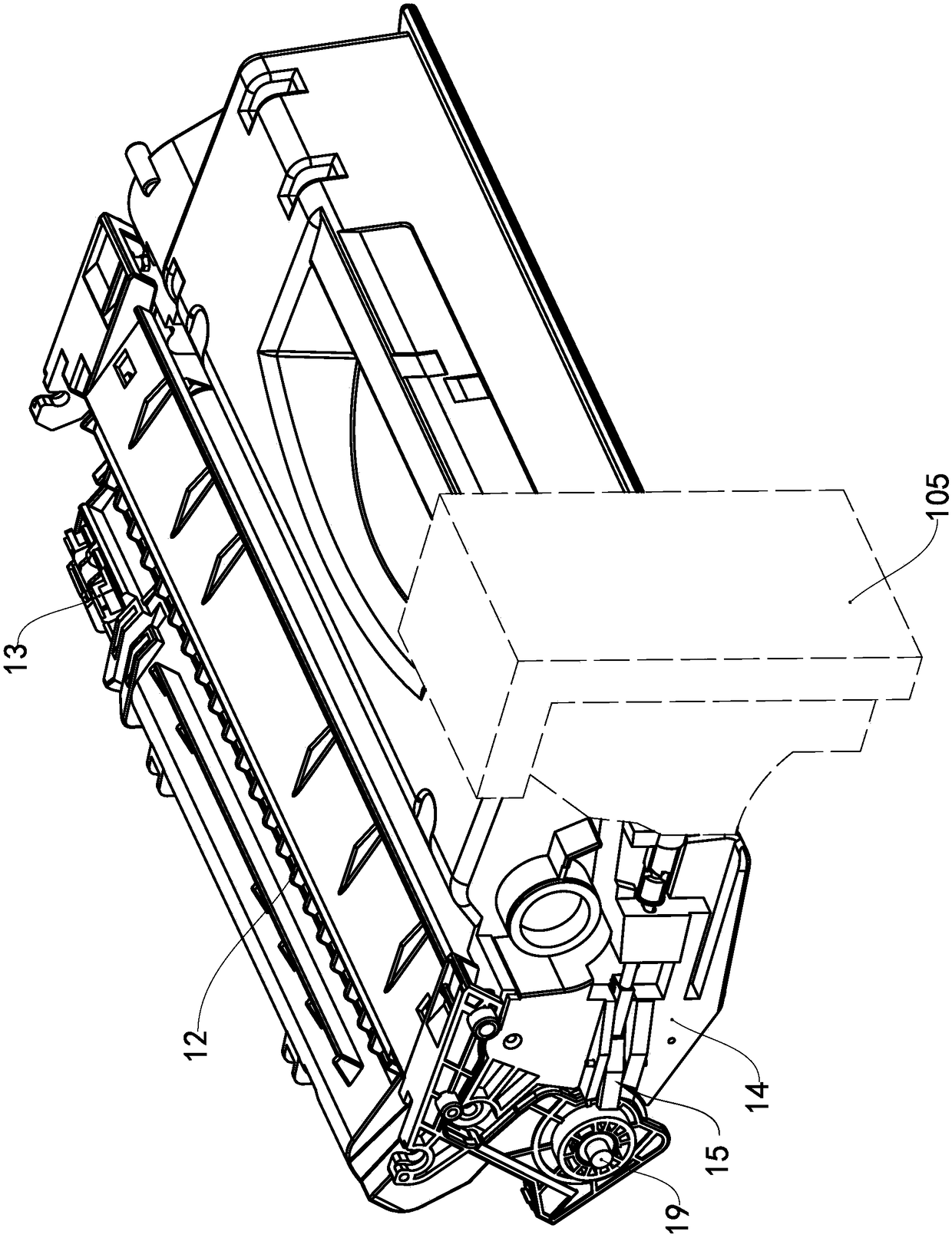
[0048] see Figure 1 to Figure 8 , the imaging device of the present embodiment is a printer, the printer has a box accommodating chamber and a door cover 105, the door cover 105 is installed on the opening side of the box accommodating chamber, and the box accommodating chamber has a first side wall 101, a second side wall 102 and a top wall , the first side wall 101 and the second side wall 102 are arranged oppositely, the top wall is located between the first side wall 101 and the second side wall 102, the top wall is provided with an electrical connection mechanism, and the electrical connection mechanism is provided with printer electrical contacts At point 104, a driving shaft 103 is disposed on the first side wall 101, and the driving shaft 103 transmits driving force to the outside. A process cartridge is detachably installed in the cartridge accommodating chamber.

[0049] The process cartridge ...


PUM


Abstract

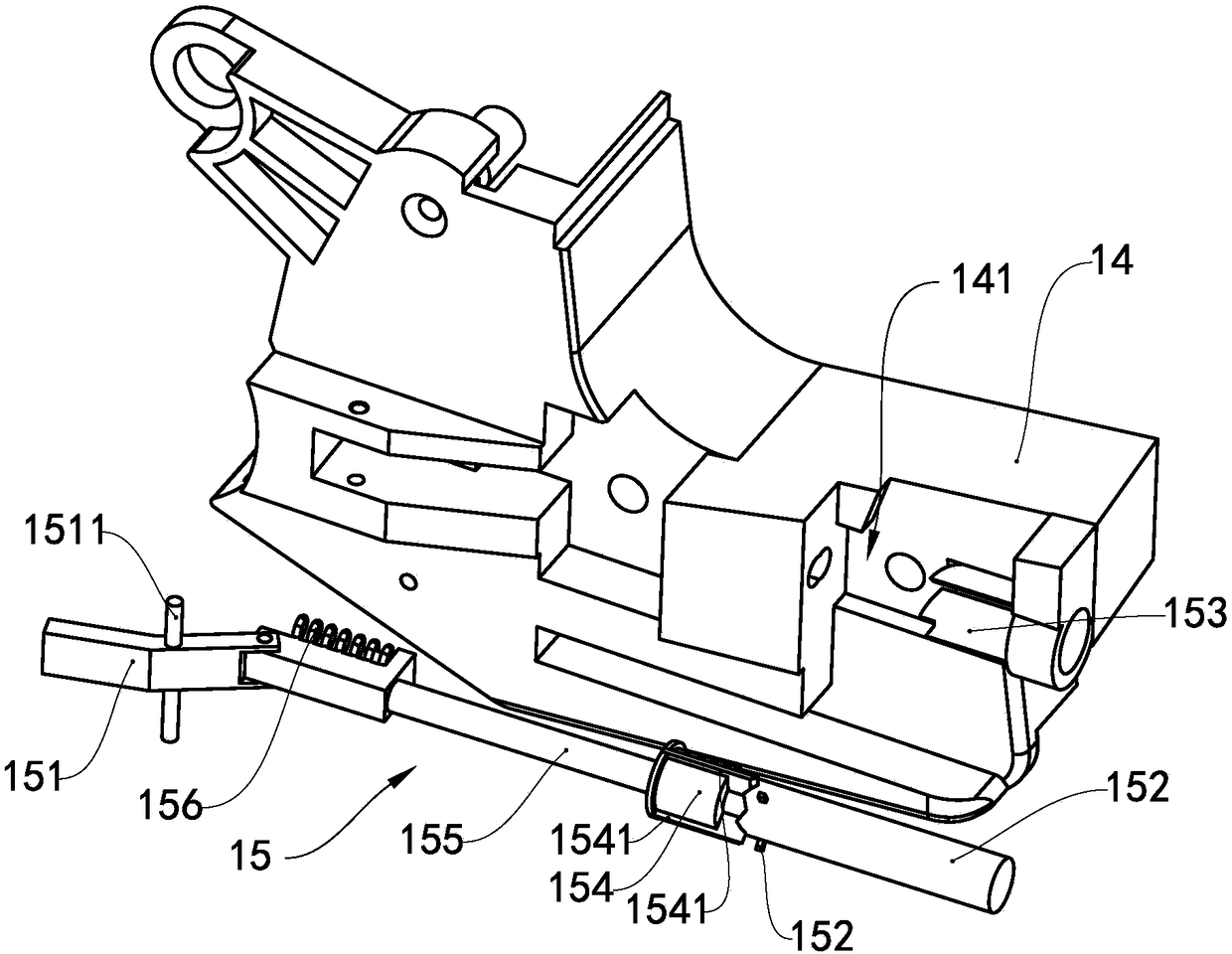
The invention provides a treatment box and an imaging device. The treatment box comprises a box body, a roller and a driving force transfer assembly, wherein the roller is rotationally supported on the first end wall and the second end wall of the box body, the driving force transfer assembly is positioned at the side of the first end wall of the box body and is in driving connection with the roller, and the driving force transfer assembly is used for receiving driving force; the treatment box also comprises driving mechanisms, the driving mechanisms are positioned at two ends of the box body,and the driving mechanisms drive the box body to move in the length direction of the box body; and each driving mechanism comprises a driving rod assembly, each driving rod assembly is provided witha force bearing end and a force applying end, the force bearing ends receive external force, and the force applying ends push the box body to move. After the force bearing ends of the driving rod assemblies are pushed, the force applying ends of the driving rod assemblies push the box body to move in the length direction of the box body, thereby realizing connection or separation of the driving force transfer assembly on the treatment box and a driving shaft in a printer. The treatment box with the driving mechanisms is simple in structure and smooth in dropping.

Description

technical field [0001] The invention relates to the technical field of electrophotographic imaging and printing, in particular to a processing box detachably installed on an imaging device and an imaging device with the processing box. Background technique [0002] An imaging device is a device that uses the principle of electrophotography to form images on printing media such as paper, including copiers, printers, fax machines, all-in-one machines, etc., and usually includes a host and a process box detachably installed in the host. Wherein, the processing box is provided with a rotating element and a rotating force transmission assembly that receives the rotating driving force provided by the main machine such as a printer. The rotating element includes at least one of a developing element, a photosensitive drum, and a charging element. After the processing box is installed on the main machine, it rotates The force transmission component cooperates with the driving mechani...

Claims


Application Information

Patent Timeline
IPC IPC(8): G03G21/18
CPCG03G21/1842G03G21/1857
Inventor 杨晓锋苏健强马力
Owner PRINT RITE UNICORN IMAGE PROD CO LTD
Learn More