A self-excited multi-point jet plasma igniter

A jet plasma and plasma technology, which is used in machines/engines, jet propulsion devices, gas turbine devices, etc., can solve the problem that the reliable ignition range cannot meet the actual needs, etc., and achieve the effect of strong ignition ability and improved ignition ability.

Active Publication Date: 2022-01-07
AIR FORCE UNIV PLA
View PDF5 Cites 0 Cited by
  • Summary
  • Abstract
  • Description
  • Claims
  • Application Information

AI Technical Summary

Problems solved by technology

Therefore, the reliable ignition range of the current plasma jet igniter in the form of a single jet hole cannot meet the actual needs.

Method used


Image

  • A self-excited multi-point jet plasma igniter
  • A self-excited multi-point jet plasma igniter
  • A self-excited multi-point jet plasma igniter

Examples


specific Embodiment

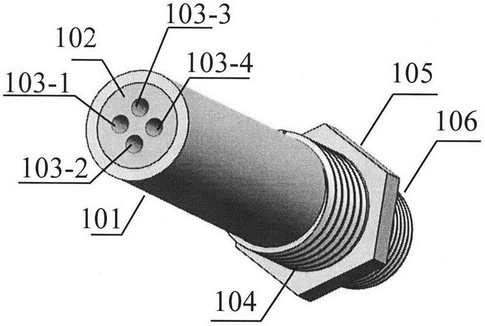
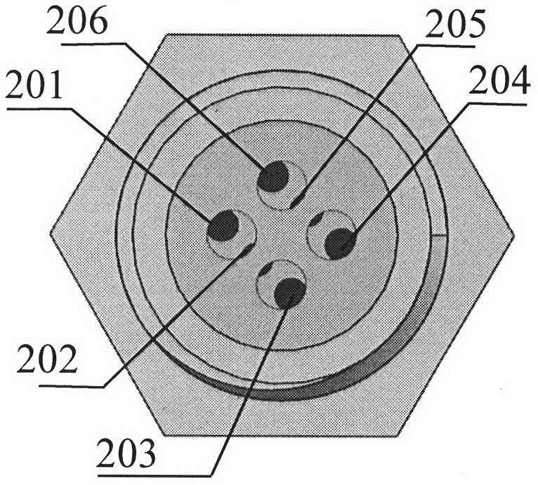
[0041] In one embodiment of the present invention, the self-excited multi-point jet plasma igniter consists of a housing 101, an insulator 102, a jet cavity (103-1 to 103-4), a mounting thread 104, a positioning hexagonal boss 105, The ignition cable is connected to thread 106 and discharge electrodes (201-206). The shell 101 is processed by high temperature resistant nickel-based superalloy, and the whole is a hollow cylindrical structure with a diameter of 18mm. The inside is processed with a through hole to install the insulator 102. The diameter of the hole is 14mm. The outside is processed with a mounting thread 104 and a positioning hexagonal boss 105 and ignition cable connection thread 106. The insulator 102 is made of high-temperature-resistant ceramics, embedded in the igniter housing 101 , and has a cylindrical shape with the same diameter as the through hole of the housing 101 . A plurality of circular cavities are processed at intervals on the end face of the ins...


PUM

PropertyMeasurementUnit
diameteraaaaaaaaaa
diameteraaaaaaaaaa
diameteraaaaaaaaaa

Abstract

A self-excited multi-point jet plasma igniter is composed of a shell (101), an insulator (102), a jet cavity (103-1-103-4), and a discharge electrode (201-206). Compared with the traditional single-jet igniter, the self-excited multi-point jet plasma igniter of the present invention can generate multiple jets, which can make up for the shortcomings of single-jet direction fixed and poor environmental adaptability. At the same time, the initial fire core formed by multiple jets forms multiple adjacent ignition sources, which effectively improves the ignition capability. In summary, the igniter of the present invention has a stronger ignition capability.

Description

technical field [0001] The invention belongs to the design field of aero-engine combustion chambers, and in particular relates to a self-excited multi-point jet plasma igniter, which is suitable for reliable ignition in aero-engine combustion chambers under extreme conditions at high altitudes. Background technique [0002] Plasma jet ignition has aerodynamic effect, thermal effect and chemical effect, and has strong ignition ability. It is considered to be the most likely technical solution to replace the current spark igniter. [0003] At present, the flight envelope of the aircraft is constantly expanding, which inevitably requires the igniter to be able to ignite the engine reliably in a wide range to ensure flight safety. When the engine operation deviates from the design condition, the combustion chamber pressure, temperature, flow rate and other parameters will inevitably be different from those in the optimum ignition condition, and the optimum ignition position wil...

Claims


Application Information

Patent Timeline
Patent Type & Authority Patents(China)
IPC IPC(8): F02C7/266
CPCF02C7/266
Inventor 张志波吴云金迪宋慧敏贾敏梁华崔巍
Owner AIR FORCE UNIV PLA
Why Eureka
Try Eureka