
Circulating feeding module, automatic feeding machine and automatic cooking equipment

A technology of automatic feeding and cyclic conveying, applied in conveyors, conveyor objects, transportation and packaging, etc., can solve problems such as waste, abnormal reclaiming by the reclaiming mechanism, and large floor space.

Inactive Publication Date: 2021-04-23
GUANGDONG ATHENE ROBOTIC TECH CO LTD
View PDF11 Cites 3 Cited by
  • Summary
  • Abstract
  • Description
  • Claims
  • Application Information

AI Technical Summary

Problems solved by technology

[0002] The common hamburger machines on the market are mostly manual feeding or the feeding station occupies a large area. The feeding machine has a complicated structure and the feeding effect is not satisfactory. Some existing ingredients like bread have a loose structure and the shape is not completely uniform. The ingredients, or other similar ingredients, are prone to sticking between the upper and lower ingredients during the stacking and feeding process, resulting in abnormal retrieving by the retrieving mechanism. This often occurs when the retrieving mechanism takes out the previous ingredient and is located below this ingredient. The ingredients stick together and are taken out and finally fall on the ground, which causes waste and pollutes the environment, which brings troubles to the picking of ingredients

Method used


Image

  • Circulating feeding module, automatic feeding machine and automatic cooking equipment
  • Circulating feeding module, automatic feeding machine and automatic cooking equipment
  • Circulating feeding module, automatic feeding machine and automatic cooking equipment

Examples


Embodiment Construction

[0033] This part will describe the specific embodiment of the present invention in detail, and the preferred embodiment of the present invention is shown in the accompanying drawings. Each technical feature and overall technical solution of the invention, but it should not be understood as a limitation on the protection scope of the present invention.

[0034] In the description of the present invention, it should be understood that the orientation descriptions, such as up, down, front, back, left, right, etc. indicated orientations or positional relationships are based on the orientations or positional relationships shown in the drawings, and are only In order to facilitate the description of the present invention and simplify the description, it does not indicate or imply that the device or element referred to must have a specific orientation, be constructed and operated in a specific orientation, and thus should not be construed as limiting the present invention.

[0035] I...


PUM


Abstract

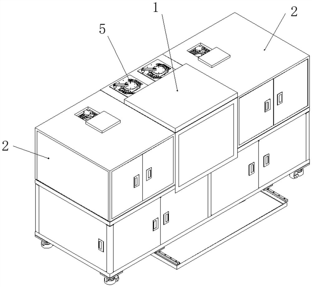
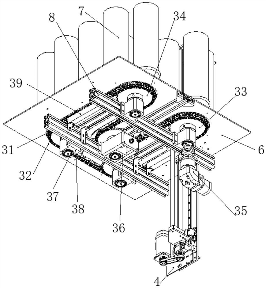
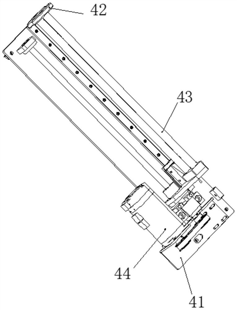
The invention discloses a circulating feeding module, an automatic feeding machine and automatic cooking equipment. The circulating feeding module mainly comprises a circulating conveying line, a carrying mechanism, a jacking mechanism and a separating mechanism. The carrying mechanism is provided with a discharging channel, wherein the discharging channel is provided with a waiting position and a discharging position in the discharging direction. The carrying mechanism is fixed to the circulating conveying line, and the separating mechanism is arranged at the waiting position of the discharging channel. After materials are jacked up by the jacking mechanism, the materials are tightened by the separating mechanism, the materials at the discharging position and the waiting position are separated by the separating mechanism, and after all the materials are discharged, the separating mechanism carries out separation, the jacking mechanism continues to carry out jacking, the work is repeated until the last material is discharged, the jacking mechanism retracts, and the circulating conveying line moves. The circulating feeding module is simple in structure, low in manufacturing cost and convenient to clean. The automatic feeding machine is composed of a plurality of cabinet bodies and a plurality of circulating feeding modules, and simultaneous discharging of various materials can be implemented. The automatic cooking equipment comprises the automatic feeding machine, and cooking can be conducted while discharging is conducted.

Description

technical field [0001] The invention relates to the field of feeding mechanisms, in particular to a cycle feeding module, an automatic feeding machine and automatic cooking equipment. Background technique [0002] The common hamburger machines on the market are mostly manual feeding or the feeding station occupies a large area. The feeding machine has a complicated structure and the feeding effect is not satisfactory. Some existing ingredients like bread have a loose structure and the shape is not completely uniform. The ingredients, or other similar ingredients, are prone to sticking between the upper and lower ingredients during the stacking and feeding process, resulting in abnormal retrieving by the retrieving mechanism. This often occurs when the retrieving mechanism takes out the previous ingredient and is located below this ingredient. The ingredients stick together and are taken out and finally fall to the ground, which causes waste and pollutes the environment, whic...

Claims


Application Information

Patent Timeline
IPC IPC(8): B65G23/04B65G23/44B65G47/74
CPCB65G23/04B65G23/44B65G47/74
Inventor 王开祥陈梓雄杨淞博廖玉城
Owner GUANGDONG ATHENE ROBOTIC TECH CO LTD
Learn More