Oxygen equipment
A kind of equipment and oxygen transmission technology, applied in the direction of mechanical equipment, transportation and packaging, separation methods, etc., can solve the problems of insufficient combustion of natural gas, reduction, waste of natural gas, etc., and achieve the effects of stable gas volume, waste reduction, and increased flow rate
- Summary
- Abstract
- Description
- Claims
- Application Information
AI Technical Summary
Problems solved by technology
Method used
Image
Examples
Embodiment 1
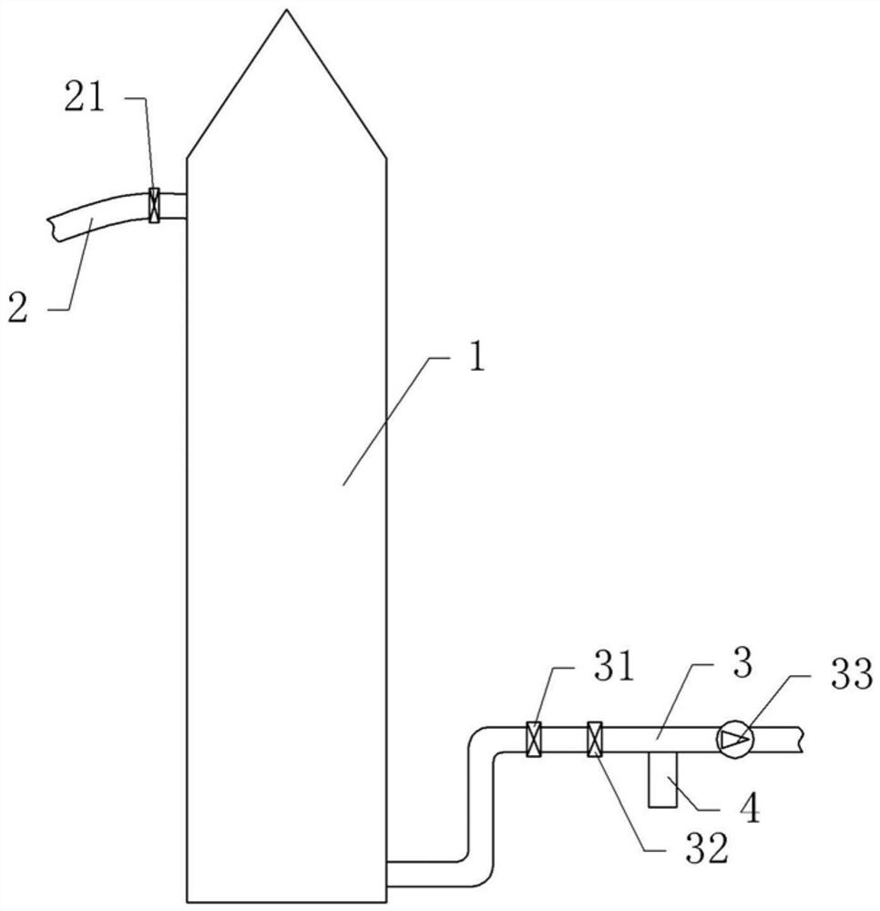
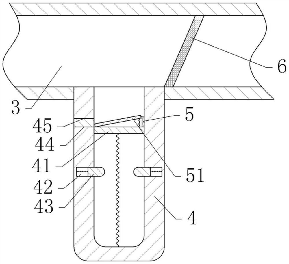
[0038] Oxygen delivery equipment, including two delivery sections, as attached figure 1As shown, the gas transmission part includes a gas storage tank 1, a gas filling pipeline 2 connected with the gas storage tank 1, and a gas transmission pipeline 3. The gas pump can realize the introduction of gas into the gas storage tank 1, and use the gas storage tank 1 to store the gas under high pressure. Also includes a gas delivery head (not shown in the figure), the gas delivery pipe 3 of the two gas delivery parts is communicated with the gas delivery head at a section away from the gas storage tank 1, and the gas delivery head includes two air inlets and an air outlet , the gas outlet can be connected with the smelting furnace to realize the input of oxygen into the smelting furnace and provide a combustion aid for the combustion of natural gas.
[0039] The gas transmission pipeline 3 is provided with a gas transmission valve 31, a one-way valve 32 and a booster pump 33 in seque...
Embodiment 2
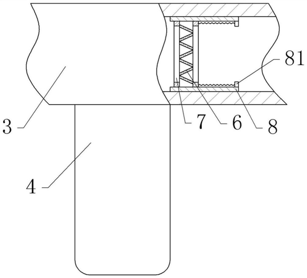
[0052] Embodiment 2 differs from Embodiment 1 only in that, as image 3 As shown, in this embodiment, the upper and lower sides of the inner wall of the gas pipeline 3 are also fixed with a mounting plate 8, and the mounting plate 8 is slidably connected with two circular brackets 7, specifically, the upper and lower ends of the bracket 7 are fixed with For the sliding block, the bottom of the upper mounting plate 8 and the top of the lower mounting plate 8 are provided with horizontal sliding grooves, and the sliding block is laterally slidably connected in the sliding grooves. The right end of the mounting plate 8 is provided with stoppers 81, and springs are respectively arranged between the two stoppers 81 and the upper part and the lower part of the bracket 7 on the right side.
[0053] There are multiple screens 6, and the two ends of each screen 6 are respectively fixed on two brackets 7, and the multiple screens 6 are sequentially connected in an S-shape. The screen c...
Embodiment 3
[0056] Embodiment 3 differs from Embodiment 2 only in that, as Figure 4 As shown, in this embodiment, the bottom of the sliding sleeve 4 is threadedly connected with a push rod 9, the top of the push rod 9 runs through the bottom of the sliding sleeve 4 and is located in the sliding sleeve 4, the top of the push rod 9 is fixed with a mounting block, and the mounting block is fixed There is a flexible film 91, the flexible film 91 is a silicone film with a thickness of 2mm, the outer periphery of the flexible film 91 is fixed to the inner wall of the sliding sleeve 4, and the fixed part of the flexible film 91 and the inner wall of the sliding sleeve 4 is located below the blocking block 43.
[0057] When the slide plate 41 slides down, it will squeeze the gas in the cavity formed between the slide plate 41, the sliding sleeve 4 and the flexible membrane 91, thereby increasing the pressure of the gas, and the continuous flow of the gas will make the gas in this part The pressu...
PUM
| Property | Measurement | Unit |
|---|---|---|
| thickness | aaaaa | aaaaa |
Abstract
Description
Claims
Application Information
 - R&D
- Intellectual Property
- Life Sciences
- Materials
- Tech Scout
- Unparalleled Data Quality
- Higher Quality Content
- 60% Fewer Hallucinations
Browse by: Latest US Patents, China's latest patents, Technical Efficacy Thesaurus, Application Domain, Technology Topic, Popular Technical Reports.
© 2025 PatSnap. All rights reserved.Legal|Privacy policy|Modern Slavery Act Transparency Statement|Sitemap|About US| Contact US: help@patsnap.com


