


Quick Research
Generate reliable direction feasibility study reports for your R&D in just a few steps.

Technical Q&A
Discover and master advanced knowledge NOW. Basics, ideas, possibilities, all at once.

Find Solutions
As an expert in R&D theories, this can generate solutions to your technical problems instantly.

Evaluate Feasibility
Analyze your overall solution with one click, know your potential R&D risks in advance.

Monitor Landscape
Get weekly tech updates, stay abreast of the latest tech innovations and key insights.
Soil sampling device and soil sampling vehicle
A sampling device and sampling vehicle technology, applied in sampling devices, measuring devices, sampling and other directions, can solve the problems of low efficiency, complicated sampling process, falling, etc., and achieve the effect of high efficiency, simple and convenient process
- Summary
- Abstract
- Description
- Claims
- Application Information
AI Technical Summary
Problems solved by technology
Method used
Image

Examples
Embodiment 1
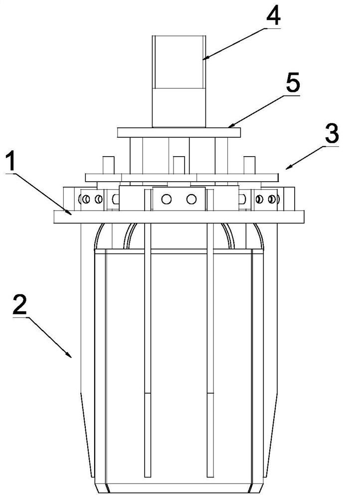
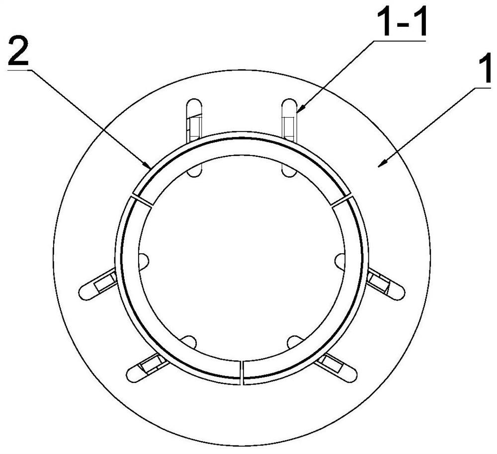
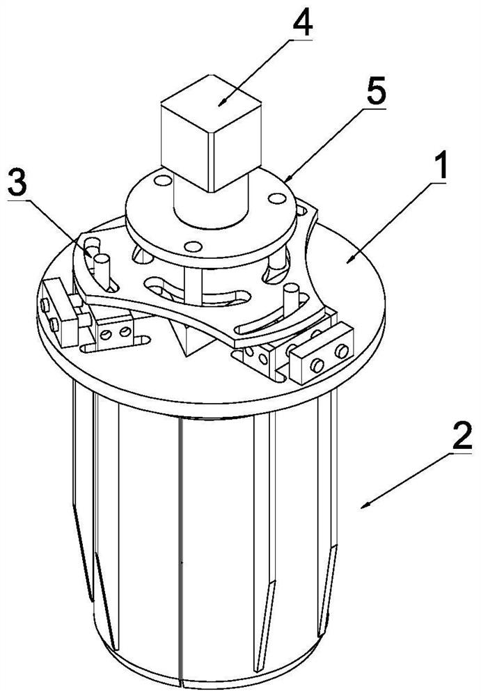
[0048] see Figure 1-Figure 3 , a soil sampling device in this embodiment, comprising a mounting base 1, three sampling clips 2 arranged below the mounting base 1 for grabbing soil samples and a sampling drive mechanism; wherein, the three sampling clips 2 are arranged along the The sampling cylinders are evenly distributed in the circumferential direction, and the sampling drive mechanism is used to drive the sampling clips 2 to move closer to each other and move away from each other along the radial direction.
[0049] see Figure 1-Figure 7 , the sampling driving mechanism includes a driving source arranged above the mounting base 1, and there is a device between the driving source and the mounting base 1 for transmitting the power of the driving source to each sampling clamp 2 and prompting three A synchronous transmission assembly 3 for synchronous movement of two sampling clips; the synchronous transmission assembly 3 includes a transmission plate 3-1 arranged on the to...
Embodiment 2
[0070] see Figure 16 , other structures in this embodiment are the same as in Embodiment 1, the difference is that: the synchronous transmission assembly 3 includes a screw 3-7, a screw nut 3-8 and 3 that cooperate with the screw 3-7 A connecting rod 3-9 arranged between the screw nut 3-8 and the slider 3-6; wherein, the upper end of the screw rod 3-7 is connected to the rotating shaft of the sampling drive motor 4, and the lower end is connected to the The mounting base 1 is connected in rotation; one end of the connecting rod 3-9 is hinged to the screw nut 3-8, and the other end is hinged to the slider 3-6. Through the above-mentioned synchronous transmission assembly 3, the sampling clip 2 can be moved towards and away from each other synchronously along the radial direction of the sampling cylinder, realizing the functions of the sampling clip 2 clamping and loosening the soil.
Embodiment 3
[0072] see Figure 17, the other structures in this embodiment are the same as in Embodiment 1, the difference is that the guide assembly includes a guide groove 3-10 arranged on the mounting seat 1 and a sliding fit with the guide groove 3-10 Sliding block 3-11; wherein, the guide groove 3-10 extends towards the center of the sampling cylinder, the lower end of the transmission rod 3-2 is fixedly connected to the upper end of the sliding block 3-11, and the sampling clip 2 The upper end of is connected with the lower end of described sliding block 3-11. By setting the guide assembly, it can ensure that the sampling clip 2 can move along the radial direction of the mounting base 1, and at the same time, it is also beneficial for the sampling clip 2 to move more stably when clamping and loosening the soil.
PUM
 Abstract
Description
Claims
Application Information
 - R&D Engineer
- R&D Manager
- IP Professional
- Industry Leading Data Capabilities
- Powerful AI technology
- Patent DNA Extraction
Browse by: Latest US Patents, China's latest patents, Technical Efficacy Thesaurus, Application Domain, Technology Topic, Popular Technical Reports.
© 2024 PatSnap. All rights reserved.Legal|Privacy policy|Modern Slavery Act Transparency Statement|Sitemap|About US| Contact US: help@patsnap.com