Multi-span overhead transmission line icing shape finding calculation method based on energy method

A technology of overhead transmission lines and calculation methods, applied in the field of transmission lines, can solve problems such as inconvenience, heavy workload, and inability to use single-span form-finding methods

Pending Publication Date: 2020-10-02
国网山西省电力公司经济技术研究院
0 Cites 0 Cited by

AI-Extracted Technical Summary

Problems solved by technology

[0004] Regarding the form-finding methods of conductors, there are currently some form-finding methods for single-span conductors, including direct iteration method, small elastic modulus method and prefabricated model update method, etc.; for multi-span overhead transmission lines with straight towers in the middle , because the insulator strings in the middle straight tower can swing off-angle, the existing single...

Method used

In the present embodiment, by step S302, single insulator string is carried out cyclic calculation successively, realized that the overall potential energy of this insulator string and its two ends transmission line reaches minimum valu...

Abstract

The invention belongs to the field of power transmission lines, and discloses a multi-span overhead power transmission line icing shape finding calculation method based on an energy method. The methodcomprises the following steps: S1, acquiring basic data and icing parameter information of initial non-icing of a multi-span overhead power transmission line; S2, calculating the horizontal stress and the original length of the initial uniced overhead transmission line, and the deflection angle of the insulator string; S3, calculating the horizontal stress of the iced overhead transmission line and the deflection angle increment of each insulator string based on the principle of minimum potential energy; and S4, constructing the icing shape of the multi-span overhead transmission line according to the deflection angle of each iced insulator string and the span, the height difference and the horizontal stress of each overhead transmission line calculated in the step S3. According to the method, the problem that modeling is complex and tedious in the multi-span overhead power transmission line shape finding process through existing finite element software can be solved, and the method is suitable for various conditions such as height difference, no height difference and multi-span different icing and can be widely applied to the field of power transmission lines.

Application Domain

Measurement devicesDesign optimisation/simulation +1

Technology Topic

Transmission lineEnergy based +8

Image

  • Multi-span overhead transmission line icing shape finding calculation method based on energy method
  • Multi-span overhead transmission line icing shape finding calculation method based on energy method
  • Multi-span overhead transmission line icing shape finding calculation method based on energy method

Examples

  • Experimental program(1)

Example Embodiment

[0080] In order to make the objectives, technical solutions, and advantages of the embodiments of the present invention clearer, the technical solutions in the embodiments of the present invention will be described clearly and completely below. Obviously, the described embodiments are part of the embodiments of the present invention, not All the embodiments; based on the embodiments of the present invention, all other embodiments obtained by those of ordinary skill in the art without creative work shall fall within the protection scope of the present invention.
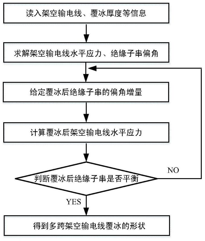
[0081] Such as Figure 1~6 As shown, the embodiment of the present invention provides an energy method-based calculation method for ice-coating shape-finding of multi-span overhead transmission lines. The multi-span overhead transmission line includes K overhead transmission lines sequentially connected by K-1 insulator strings, including The following steps:
[0082] S1. Obtain the initial uniced basic data and ice-coated parameter information of the multi-span overhead transmission line.
[0083] Specifically, in step S1, the acquired basic data and icing parameter information of the multi-span overhead transmission line without ice coating include:
[0084] y mk , H k , L k , P k , P bk , E k , A k , Γ k , ΔT k (k=1……K);
[0085] G j , C j (j=1……K-1);
[0086] Where y mk Indicates the maximum sag of overhead transmission line k under the initial uniced condition; h k Indicates the height difference between two adjacent suspension points of overhead transmission line k under the initial unicing condition; l k Indicates the span between two adjacent suspension points of overhead transmission line k under the initial unicing condition; p k Indicates the specific load of the overhead transmission line k without initial ice coating; p bk Indicates the specific load of the overhead transmission line k after icing; E k Represents the modulus of elasticity of overhead transmission line k; A k Indicates the cross-sectional area of ​​overhead transmission line k; γ k Represents the thermal expansion coefficient of overhead transmission line k; ΔT k Indicates the temperature increment difference before and after icing of the overhead transmission line k; G j Represents the gravity of the insulator string j; c j Indicates the length of the insulator string j.
[0087] Such as figure 2 As shown, in this embodiment, the left end point of each span overhead transmission line is used as the coordinate origin to establish a local rectangular coordinate system. The horizontal right direction is the positive x direction, and the vertical upward direction is the positive y direction. During the icing process, it is assumed that the gravity and length of the insulator string remain unchanged, and the elastic modulus of the insulator string is not considered.
[0088] S2. Calculate the initial horizontal stress and original length of the uniced overhead transmission line and the deflection angle of the insulator string.
[0089] In step S2, the specific method for calculating the horizontal stress and original length of the initial uniced overhead transmission line and the deflection angle of the insulator string is: according to the relationship between the maximum sag of the overhead transmission line and the initial horizontal stress when the initial uniced The iterative method calculates the initial horizontal stress of each overhead transmission line without ice coating, and then calculates the original length of each overhead transmission line without ice coating according to the initial horizontal stress; the static balance equation is solved by the Newton iteration method, and the initial uncovered The deflection angle of each insulator string on ice. Further, the specific steps are:
[0090] S21: List the formula for calculating the parameters required for the initial horizontal stress, that is, the formula for calculating the original length of each overhead transmission line when the initial icing is not applied, specifically:
[0091]
[0092] among them: x mk It is the abscissa corresponding to the maximum sag point of the k-th overhead transmission line (k=1...K) in the local coordinate system when the ice is not initially covered, σ k Is the initial horizontal stress of the k-th overhead transmission line when it is initially uniced, such as figure 2 Shown, p k Is the specific load of the overhead transmission line k under the initial unicing condition; h k It is the height difference between two adjacent suspension points of overhead transmission line k along the load direction under the initial unicing condition; l k It is the vertical projection distance between two adjacent suspension points of the overhead transmission line k under the initial unicing condition.
[0093] S22: Use the Newton iteration method to solve the equation (1), the initial horizontal stress σ of the overhead transmission line k (k=1...K) can be obtained respectively k , And then can calculate the original length of each overhead transmission line when the initial non-icing, the calculation formula is:
[0094]
[0095] Where s k Is the original length of the k-th overhead transmission line (k=1...K) when it is initially uniced, E k Is the elastic modulus of overhead transmission line k.
[0096] S23: List calculation subsequent parameters θ j The required equation, the static balance equation:
[0097]
[0098] among them:
[0099] θ j Indicates the deflection angle of the j-th insulator string (j=1...K-1) when the initial non-icing is applied, such as image 3 Shown. σ j And σ j+1 Respectively represent the initial horizontal stress of the overhead transmission line at both ends of the j-th insulator string when the initial non-icing, A j And A j+1 Respectively represent the cross-sectional area of ​​the overhead transmission line at both ends of the j-th insulator string, p j And p j+1 Respectively represent the specific load of the overhead transmission line at both ends of the j-th insulator string under the initial uniced condition, x mj And x mj+1 Respectively represent the abscissa corresponding to the maximum sag point of the overhead transmission line at both ends of the j-th insulator string in the local coordinate system when the initial ice is not covered; G j Represents the gravity of the j-th insulator string, c j Indicates the length of the jth insulator string.
[0100] S24: Take the initial horizontal stress σ of the overhead transmission line k (k=1...K) obtained in S22 when the initial ice is not covered k , And other parameters are substituted into equation (3). Use the Newton iteration method to solve equation (3), and obtain the deflection angle θ of the initial uniced insulator string j (j=1...K-1) j.
[0101] S3, such as image 3 As shown, calculating the horizontal stress of the overhead transmission line after ice coating and calculating the deflection angle increment of each insulator string includes the following steps:
[0102] S301. Corresponding to the deflection angle of all insulator strings in the uniced state and the pitch and height difference of the overhead transmission line as the initial values ​​of the deflection angle of the insulator string in the icing state and the pitch and height difference of the overhead transmission line respectively.
[0103] S302. Assign values ​​to the deflection angles of each insulator string after icing in sequence, and calculate the height difference, span and horizontal stress of the overhead transmission lines at both ends of each insulator string after icing; then, based on the principle of minimum potential energy, use the rule of thirds to calculate, Obtain the deflection angle of each insulator string after icing in turn; among them, each time the deflection angle value of the insulator string after icing is calculated, it will be saved as the initial value of the deflection angle of the insulator string in the icing state. The calculated span and height difference of the overhead transmission line at both ends of the insulator string are saved as the initial value of the span and height difference of the overhead transmission line.
[0104] Specifically, in this embodiment, the step S302 includes the following steps:
[0105] S3021, assign a value to the deflection angle of each insulator string after icing;
[0106] S3022, according to the initial value of the deflection angle and the assigned deflection angle of the first insulator string after icing, and the initial value of the span and height difference of the overhead transmission lines at both ends, calculate the overhead of the first insulator string after icing Transmission line pitch and height difference;
[0107] Specifically, the calculation formulas for the span and height difference of the overhead transmission lines at both ends of the insulator string after ice coating are:
[0108] l bj =l' bj +c j (sinθ bj -sinθ' bj ); (4)
[0109] l bj+1 =l' bj+1 -c j (sinθ bj -sinθ' bj ); (5)
[0110] h bj =h' bj -c j (cosθ bj -cosθ' bj ); (6)
[0111] h bj+1 =h' bj+1 +c j (cosθ bj -cosθ' bj ); (7)
[0112] Where l bj And l bj+1 Respectively represent the span of the overhead transmission lines j and j+1 at both ends of the j-th insulator string in the icing state; h bj And h bj+1 Respectively represent the height difference between the overhead transmission lines j and j+1 at both ends of the j-th insulator string in the ice-coated state; l' bj And l′ bj+1 Respectively represent the initial value of the j and j+1 spans of the overhead transmission lines at both ends of the j-th insulator string under icing conditions; h′ bj And h′ bj+1 Respectively represent the initial value of the height difference between the overhead transmission lines j and j+1 at both ends of the j-th insulator string in the icing state; θ bj And θ′ bj Respectively indicate the deflection angle and the initial value of the deflection angle of the insulator in the icing state; c j Indicates the length of the jth insulator string.
[0113] S3023. Calculate the horizontal stress of the overhead transmission line at both ends of the first insulator string after icing based on the span and height difference obtained in step S3022, and according to the level of the overhead transmission line at both ends of the first insulator string after icing Stress, calculate the total potential energy U of the first insulator string and the transmission line at both ends.
[0114] The calculation method for the horizontal stress of the overhead transmission line at both ends of the insulator string after icing is: the pitch and height difference parameters of the overhead transmission line at both ends of the insulator string calculated in step S3022 are brought into the equation set, and the equation set is solved by the Newton iteration method. Obtain the horizontal stress of the overhead transmission line at both ends of the insulator string after icing, and the equations are:
[0115]
[0116]
[0117] among them:
[0118]
[0119]
[0120]
[0121] σ bj And σ bj+1 Respectively represent the horizontal stress of the overhead transmission lines j and j+1 at both ends of the j-th insulator string after icing; x mbj And x mbj+1 They are the maximum sag points of overhead transmission lines j and j+1 at both ends of the j-th insulator after ice coating, and the corresponding abscissas in the local coordinate system; σ bj And σ bj+1 They are the horizontal stresses of overhead transmission lines j and j+1 at both ends of the j-th insulator after ice coating; γ j And γ j+1 Respectively represent the thermal expansion coefficients of the overhead transmission lines j and j+1 at both ends of the j-th insulator after ice coating; ΔT j And ΔT j+1 Respectively represent the temperature increment difference of the overhead transmission lines j and j+1 at both ends of the jth insulator before and after icing; E j And E j+1 Respectively represent the elastic modulus of the overhead transmission lines j and j+1 at both ends of the jth insulator; s bj And s bj+1 Respectively represent the lengths of overhead transmission lines j and j+1 at both ends of the j-th insulator string after icing; h bj And h bj+1 Respectively represent the height difference between the overhead transmission lines j and j+1 at both ends of the j-th insulator string after icing; p bj And p bj+1 Respectively represent the specific load of the overhead transmission line at both ends of the j-th insulator string after icing; l bj And l bj+1 Respectively represent the span of the overhead transmission lines j and j+1 at both ends of the j-th insulator string after icing; s j And s j+1 Respectively expressed as the original lengths of the overhead transmission lines j and j+1 at both ends of the j-th insulator string when the initial non-icing was applied;
[0122] In the step S3023, the formula for calculating the overall potential energy U of the insulator string and the transmission lines at both ends thereof is:
[0123] U=U 1 (j)+U 2 (j)+U 2 (j+1)+U 3 (j)+U 3 (j+1); (10)
[0124] Including:
[0125]
[0126]
[0127]
[0128]
[0129]
[0130] In formulas (10)~(15), c j Represents the length of the jth insulator string, θ bj Indicates the deflection angle of the jth insulator string, x mbj And x mbj+1 They are the abscissas corresponding to the maximum sag points of the overhead transmission lines j and j+1 at both ends of the j-th insulator after ice coating in the local coordinate system; A j And A j+1 Respectively represent the cross-sectional area of ​​the overhead transmission line at both ends of the j-th insulator string; E j And E j+1 Respectively represent the elastic modulus of the overhead transmission lines j and j+1 at both ends of the j-th insulator; U 1 (j) represents the gravitational potential energy of the jth insulator; U 2 (j) and U 2 (j+1) respectively represent the elastic potential energy of the overhead transmission lines j and j+1 at both ends of the jth insulator; U 3 (j) and U 3 (j+1) respectively represent the gravitational potential energy of overhead transmission lines j and j+1 at both ends of the j-th insulator. The zero-gravity potential energy surface of the insulator string j and the transmission lines j and j+1 is the plane where the hanging point on the insulator string j is located.
[0131] S3024. In the range of [-0.5,0.5], use the method of thirds to change the deflection angle assignment of the insulator string, and repeat steps S3022 to S3023 until the minimum value of the overall potential energy U of the insulator string and the transmission lines at both ends is calculated , And then terminate the cycle. At the same time, assign the deflection angle of the first insulator string before the end of the cycle and the calculated span and height difference of the overhead transmission lines at both ends as the deflection angle of the first insulator string in the icing state The initial values ​​of the pitch and height difference of the overhead transmission lines at both ends are saved, and step S3025 is entered.
[0132] Among them, the initial value of the above-mentioned storage deflection angle, gear distance and height difference is given l' bj = L bj , L' bj+1 = L bj+1 , H' bj =h bj , H' bj+1 =h bj+1 , Θ' bj =θ bj , Where l bj And l bj+1 Respectively represent the span of the overhead transmission lines j and j+1 at both ends of the j-th insulator string after icing; l′ bj And l′ bj+1 Respectively represent the initial value of the span j and j+1 of the overhead transmission lines at both ends of the j-th insulator string after icing; h bj And h bj+1 Respectively represent the height difference between the overhead transmission lines j and j+1 at both ends of the j-th insulator string after icing; h′ bj And h′ bj+1 Respectively represent the initial value of the height difference between the overhead transmission lines j and j+1 at both ends of the j-th insulator string after icing.
[0133] S3025. Repeat the calculation process of steps S3022~S3024 for the second to K-1th insulator strings until the deflection angles of all insulator strings after icing are obtained, as well as the span, height difference and level of the overhead transmission lines at both ends stress.
[0134] S303. Repeat step S302, again based on the principle of minimum potential energy, use the rule of thirds to calculate, and obtain the deflection angles of each insulator string after icing in turn; then judge whether the deflection angles of the insulators calculated twice meet the condition: max|θ bj -θ pj |> δθ, (j=1……K-1), where θ bj Indicates the deflection angle of the jth insulator string after icing obtained this time, θ pj It represents the deflection angle of the jth insulator string after icing calculated last time, and δθ represents the deflection angle difference threshold; if it is satisfied, return to step S302 for recalculation; otherwise, the calculation ends, and step S4 is entered.
[0135] In this embodiment, through step S302, a single insulator string is sequentially calculated cyclically, so that the overall potential energy of the insulator string and the transmission lines at both ends reaches the minimum value, that is, the balance is reached. Then, through step S303, the single The insulator strings are calculated cyclically in turn, and the balance of all insulator strings is achieved through the set deflection angle threshold conditions.
[0136] S4. According to the deflection angle of each insulator string after icing calculated in step S3 and the span, height difference and horizontal stress of each overhead transmission line, construct the shape of the icing of the multi-span overhead transmission line.
[0137] Specifically, the specific steps for constructing the ice-coated shape of a multi-span overhead transmission line from the calculated data are:
[0138] S401: The entire multi-span overhead transmission line uses the leftmost end point of the overhead transmission line as the coordinate origin to establish a global rectangular coordinate system, the horizontal right is the positive x direction, and the vertical upward is the positive y direction, such as Figure 5 Shown
[0139] S402: According to the deflection angle of each insulator string after icing obtained in step S3, the span, height difference and horizontal stress of each overhead transmission line are calculated to obtain the ordinate of each overhead transmission line in the global coordinate system after icing. The calculation formula is :
[0140]
[0141] Where: y bk Represents the ordinate of the kth overhead transmission line in the global coordinate system after icing, l b0 =h b0 =0; σ bk Indicates the horizontal stress of the overhead transmission line k after icing; p bk Indicates the specific load of the overhead line k after icing; x bk Represents the abscissa of the overhead line k after icing; l bi Indicates the pitch of the overhead line i after icing; h bi Indicates the height difference of the overhead line i after icing;
[0142] S403: Calculate the abscissa x of each insulator string in the global coordinate system after icing bj And the ordinate y bj , The calculation formula is:
[0143]
[0144]
[0145] Where c j Represents the length of the jth insulator string, θ bj Indicates the deflection angle of the jth insulator string after icing calculated in step S3.
[0146] The overhead transmission line uses LGJ-240/30, and the multi-span overhead transmission line information and icing information are shown in Table 1:
[0147] Table 1 Parameters and icing information of double-span overhead transmission lines
[0148]
[0149] Bringing the data in Table 1 into the above embodiment, the shape of the multi-span overhead transmission line can be calculated, such as Image 6 Shown. Table 2 shows the results of ice-coating form finding using finite element software and the method in this paper:
[0150] Table 2 Comparison of ice-coating form-finding results of various methods
[0151]
[0152] It can be seen from Table 2 that the calculation method of the present invention is highly consistent with the results of the finite element analysis software. However, the present invention can simplify the existing finite element software to model complex, multi-span overhead transmission line form-finding processes. Trivial question.
[0153] Finally, it should be noted that the above embodiments are only used to illustrate the technical solutions of the present invention, but not to limit them; although the present invention has been described in detail with reference to the foregoing embodiments, those of ordinary skill in the art should understand: It is still possible to modify the technical solutions described in the foregoing embodiments, or equivalently replace some or all of the technical features; and these modifications or replacements do not make the essence of the corresponding technical solutions deviate from the technical solutions of the embodiments of the present invention. range.

PUM

no PUM

Description & Claims & Application Information

We can also present the details of the Description, Claims and Application information to help users get a comprehensive understanding of the technical details of the patent, such as background art, summary of invention, brief description of drawings, description of embodiments, and other original content. On the other hand, users can also determine the specific scope of protection of the technology through the list of claims; as well as understand the changes in the life cycle of the technology with the presentation of the patent timeline. Login to view more.
Why Eureka
Try Eureka