Water-cooling and air-cooling electronic power heat dissipation device

A technology of electronic power and heat dissipation devices, which is applied in the direction of cooling/ventilation/heating transformation, electrical components, electrical equipment structural parts, etc., can solve problems such as single, burnt out, and affect the stable operation of electronic equipment, so as to avoid wear gaps and ensure The effect of cooling effect

Inactive Publication Date: 2020-10-02
江苏海鼎电气科技有限公司
View PDF0 Cites 1 Cited by
  • Summary
  • Abstract
  • Description
  • Claims
  • Application Information

AI Technical Summary

Problems solved by technology

[0002] At present, the operation of electronic equipment will generate heat, which will cause the temperature of the entire equipment to rise, and the excessive temperature will greatly affect the stable operation of electronic equipment, and even burn out in severe cases, which requires cooling and heat dissipation devices. To cool down, the existing cooling and heat dissipation devices generally include a heat dissipation plate, heat dissipation fins, and an exhaust fan. The entire cooling and heat dissipation device is installed in the chassis, and one side of the heat dissipation plate is abutted against the back of the electronic device, and the other side of the heat dissipation plate is mounted on the back of the electronic device. Evenly distributed heat dissipation fins are installed on the side for heat dissipation, and the exhaust fan is used to increase the discharge of hot air flow and improve the heat dissipation effect. Sometimes electronic equipment is directly inserted into the heat dissipation fins for heat dissipation, but the existing heat dissipation method is relatively simple. The heat dissipation efficiency of the sheet exhaust method is average. In addition, different electronic chassis need to install heat dissipation devices of different thicknesses, especially ultra-thin chassis, which requires adaptive production, which greatly restricts the use of heat dissipation devices.

Method used


Image

  • Water-cooling and air-cooling electronic power heat dissipation device
  • Water-cooling and air-cooling electronic power heat dissipation device
  • Water-cooling and air-cooling electronic power heat dissipation device

Examples


Embodiment Construction

[0019] The content of the present invention will be further described in detail below in conjunction with the accompanying drawings.

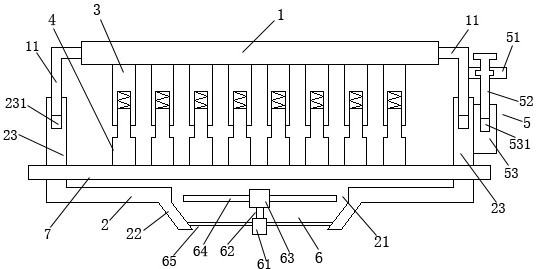
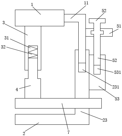
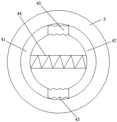
[0020] Such as Figures 1 to 3 As shown, a water-cooled air-cooled electronic power heat dissipation device includes a heat dissipation plate 1, a positioning heat dissipation fin 3, a floating heat dissipation fin 4, a telescopic drive mechanism 5, an abutting cooling water plate 7, a lower connecting plate 2, and an exhaust mechanism 6. The lower connection plate 2 is installed relatively parallel directly under the heat dissipation plate 1; the lower connection plate 2 is installed directly below the heat dissipation plate 1 floating up and down; the telescopic drive mechanism 5 is installed on the heat dissipation plate 1 and the lower connection One side of the plate 2; the telescopic drive mechanism 5 drives the lower connecting plate 2 to move up and down; the lower end surface of the heat dissipation plate 1 is uniformly and vertically ...


PUM


Abstract

The invention discloses a water-cooling and air-cooling electronic power heat dissipation device which comprises a heat dissipation plate, positioning heat dissipation fins, floating heat dissipationfins, a telescopic driving mechanism, an abutting cooling water plate, a lower connecting plate and an exhaust mechanism. In order to adapt to the space sizes of different cases, a floating telescopicstructure is designed, the water-cooling and air-cooling electronic power heat dissipation device telescopes and slides at the lower ends of the positioning cooling fins via the floating heat dissipation fins, and the lower connecting plate floats and stretches out and draws back below the heat dissipation plate, so that the whole structure can adapt to the cases with different thicknesses afterstretching out and drawing back.

Description

technical field [0001] The invention relates to a water-cooled air-cooled electronic power radiator. Background technique [0002] At present, the operation of electronic equipment will generate heat, which will cause the temperature of the entire equipment to rise, and the excessive temperature will greatly affect the stable operation of electronic equipment, and even burn out in severe cases, which requires cooling and heat dissipation devices. To cool down, the existing cooling and heat dissipation devices generally include a heat dissipation plate, heat dissipation fins, and an exhaust fan. The entire cooling and heat dissipation device is installed in the chassis, and one side of the heat dissipation plate is abutted against the back of the electronic device, and the other side of the heat dissipation plate is mounted on the back of the electronic device. Evenly distributed heat dissipation fins are installed on the side for heat dissipation, and the exhaust fan is used...

Claims


Application Information

Patent Timeline
Patent Type & Authority Applications(China)
IPC IPC(8): H05K7/20
CPCH05K7/20145H05K7/20218H05K7/20409
Inventor 陶勇
Owner 江苏海鼎电气科技有限公司
Why Eureka
Try Eureka