Semi-enclosed permanent magnet motor cooling system
A permanent magnet motor and cooling system technology, which is applied in the direction of cooling/ventilation devices, electric components, electromechanical devices, etc., to achieve the effects of saving system energy consumption, high reliability design, and high power density
- Summary
- Abstract
- Description
- Claims
- Application Information
AI Technical Summary
Problems solved by technology
Method used
Image
Examples
Embodiment 1
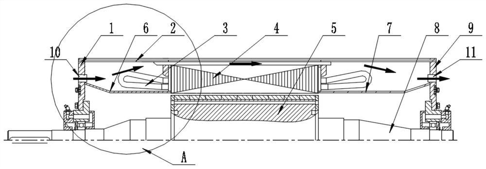
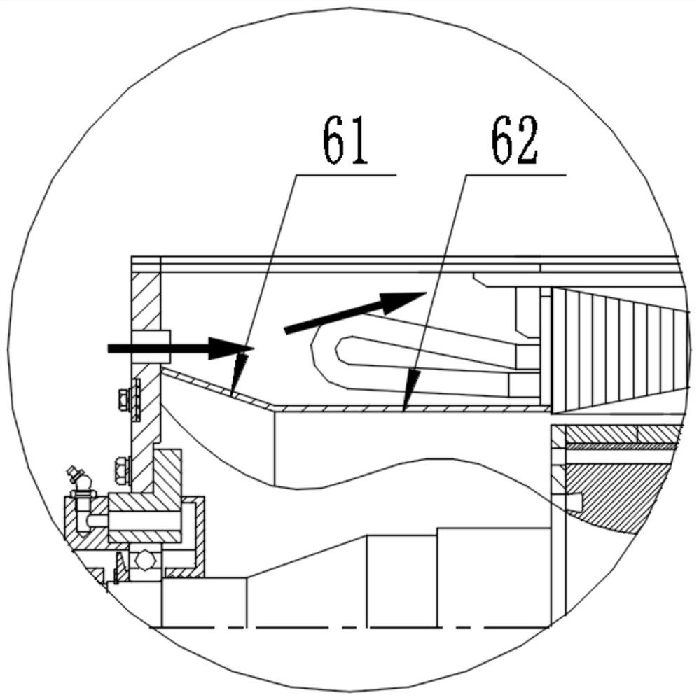
[0049] Refer to attached figure 1 , which is a cross-sectional schematic diagram of a specific embodiment of the semi-closed permanent magnet motor cooling system of the present invention, the cooling system includes a stator, a rotor 5, a rotating shaft 8 and a casing 2, wherein the stator includes a stator core 4 . Stator winding 3. The stator winding is arranged at both ends of the stator core, and the stator core is fixed on the inner wall of the casing. The system also includes the air inlet 10, the air outlet 11 and the rotor sleeve structure. The rotor sleeve structure is set On the outside of the rotor 5, to isolate the rotor and the stator; the air inlet hole and the air outlet hole respectively pass through the first end cover 1 and the second end cover 9 of the casing 2, and the air inlet hole 10 and the air outlet hole 11 Located between the rotor sleeve structure and the casing 2, it is used to realize the air guide of the externally installed air cooling device o...
Embodiment 2
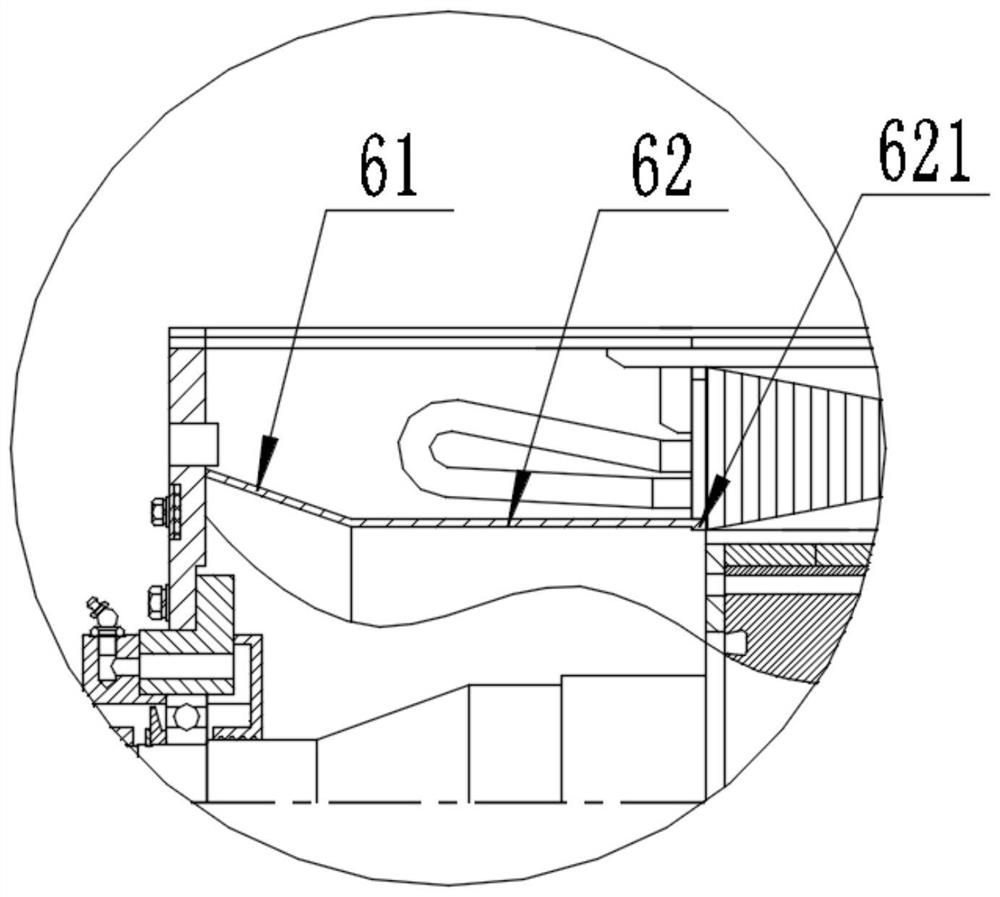
[0057] Refer to attached image 3 , shown as figure 1 The structural diagram of the second specific embodiment of the partial enlarged view in A, on the basis of the first embodiment, the end of the second structure 62 away from the first structure 61 is provided with a second protrusion 621, and the second protrusion is far away from the first structure 61. The side of a structure is arranged parallel to the surface to be connected to the first end of the stator core, and the second protrusion is arranged perpendicular to the axis of the rotating shaft, that is, the second protrusion in this embodiment protrudes inward relative to the second structure out of the setting to increase the contact area with the first end of the stator core; the first tubular structure is bonded to the first end cover through the end of the first structure away from the second end cover, and is close to the stator core through the second protrusion One side is bonded to the first end of the stato...
Embodiment 3
[0060] Refer to attached Figure 4 , shown as figure 1 The structural diagram of the third specific embodiment of the partial enlarged view of A, on the basis of the second embodiment, the end of the first structure away from the second structure is provided with a first protrusion 611, and the first protrusion 611 is far away from the second The side part of the structure is arranged parallel to the first end cover, and the first protrusion is arranged perpendicular to the axis of the rotating shaft, that is, the first protrusion in this embodiment protrudes outward relative to the first structure, increasing the distance from the first end cap. The contact area of an end cover; the first tubular structure is bonded to the first end cover through the first protrusion 611 provided on the first structure, and the first end of the stator core is connected to the first end of the stator core through the second protrusion provided on the second structure (that is, the tooth por...
PUM
 Abstract
Description
Claims
Application Information
 - R&D
- Intellectual Property
- Life Sciences
- Materials
- Tech Scout
- Unparalleled Data Quality
- Higher Quality Content
- 60% Fewer Hallucinations
Browse by: Latest US Patents, China's latest patents, Technical Efficacy Thesaurus, Application Domain, Technology Topic, Popular Technical Reports.
© 2025 PatSnap. All rights reserved.Legal|Privacy policy|Modern Slavery Act Transparency Statement|Sitemap|About US| Contact US: help@patsnap.com


