Eureka AIR delivers breakthrough ideas for toughest innovation challenges, trusted by R&D personnel around the world.

cooling engine block

An engine block and cylinder block technology, which is applied in engine components, machines/engines, hot gas variable capacity engine devices, etc., can solve problems such as inability to effectively reduce the temperature of the cylinder block, accelerate piston ring wear, and hinder development.

Active Publication Date: 2018-05-22
太仓市海丰金属制品有限公司
View PDF4 Cites 0 Cited by
  • Summary
  • Abstract
  • Description
  • Claims
  • Application Information

AI Technical Summary

Problems solved by technology

[0002] Traditionally, the wall thickness of the cylinder that relies on the expansion of high-temperature gas to do work is thicker, especially the larger the cylinder diameter, the greater the pressure of the working gas, and the thicker the cylinder wall thickness required. The internal cooling method of the cylinder cannot meet the needs, which hinders the development of cylinders with large bore, high pressure and high output power, especially the hot air engine in which the piston reciprocates without oil lubrication in the cylinder, which cannot effectively reduce the temperature of the cylinder and will Accelerated wear of piston rings, shortening service life

Method used


Image

  • cooling engine block
  • cooling engine block
  • cooling engine block

Examples


Embodiment 1

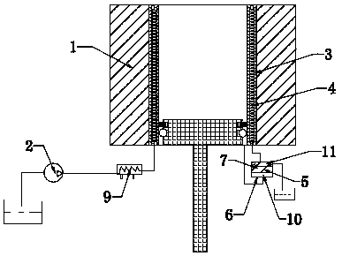
[0022] Such as figure 1 As shown, the cooling engine cylinder block of the present invention includes a cylinder block 1 in which a high-pressure working fluid gas is expanded. The inner cavity of the cylinder block 1 has a jacket 3 embedded on the inner wall of the cylinder, and the jacket 3 has a fluid inner cavity. , The fluid cavity forms a cooling channel 4, which connects the high-pressure oil cooler 9 and the supercharger, and the cooling channel 4 is connected in series with the high-pressure oil cooler 9 and the supercharger. The supercharger is one Oil pump 2, cooling channel 4 is provided with an oil outlet, cooling channel 4 is equipped with an overflow valve 5 at the oil outlet, so that the coolant cooled by the cooler flows through the cooling channel 4 to cool the cylinder block Return to the oil tank through the overflow valve. The overflow valve is a gas-liquid balanced overflow valve. The gas-liquid balanced overflow valve includes a valve body 6 in which a col...

Embodiment 2

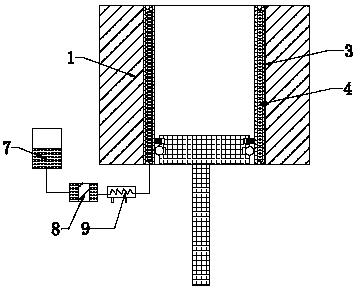
[0024] Such as figure 2 As shown, the cooling engine cylinder block of the present invention includes a cylinder block 1 in which a high-pressure working fluid gas is expanded. The inner cavity of the cylinder block 1 has a jacket 3 embedded on the inner wall of the cylinder, and the jacket 3 has a fluid inner cavity. , The fluid cavity forms a cooling channel 4, which connects the high-pressure oil cooler 9 and the supercharger, and the cooling channel 4 is connected in series with the high-pressure oil cooler 9 and the supercharger. The supercharger is one The external accumulator 7, the high-pressure working fluid gas stored in the accumulator 7, the accumulator 7 applies a balanced pressure to the coolant in the cooling channel 4, and the high-pressure oil cooler 9 and the accumulator 7 are arranged between There is a balancing piston 8. The high-pressure working medium in the cylinder 1 pushes the balancing piston 8 to apply a balanced pressure to the coolant in the coolin...

Embodiment 3

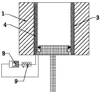
[0026] Such as image 3 As shown, the cooling engine cylinder block of the present invention includes a cylinder block 1 in which a high-pressure working fluid gas is expanded. The inner cavity of the cylinder block 1 has a jacket 3 embedded on the inner wall of the cylinder, and the jacket 3 has a fluid inner cavity. , The fluid cavity forms a cooling channel 4, the cooling channel 4 is connected to the high-pressure oil cooler 9 and the supercharger, the cooling channel 4 is connected in series with the high-pressure oil cooler 9 and the supercharger, and the cooling channel 4 is connected in series with the high pressure The oil cooler 9 and the supercharger. The supercharger is the inner cavity of the cylinder block 1. The high-pressure working medium gas in the inner cavity of the cylinder block 1 applies a pressure to the coolant in the cooling channel 4 to balance The pressure difference between the cooling channel 4 and the inner cavity of the cylinder block 1. A balance...


PUM


Abstract

The invention discloses a cylinder body structure of a heat engine, and particularly relates to an efficient cooling engine cylinder. The efficient cooling engine cylinder comprises a cylinder body with high-pressure working medium gas expansion inside, an inner cavity of the cylinder body is provided with a jacket embedded on the inner wall of the cylinder body, the jacket is provided with a fluid inner cavity, and a cooling flow way is formed in the fluid inner cavity and is connected with a high-pressure oil cooler and a pressurizing device. By the adoption of the structure, the jacket with a circular cooling channel is arranged in the inner cavity of the cylinder body, the circular cooling channel is sequentially in series connection with a high-pressure oil cooler and the pressurizing device or directly connected with the high-pressure oil cooler and the pressurizing device, and accordingly through introducing of high-pressure cooling oil into the circular cooling flow way, the oil pressure and the pressure of high-pressure working media in the inner cavity of the cylinder body are equivalent; thus, the thickness of the inner cylinder wall can be smaller, the temperature brought by wear between a piston ring and the inner cylinder wall can be absorbed, and according to the efficient cooling cylinder body of the heat engine, no matter how much the thickness of the cylinder body is increased, the cooling effect is not affected.

Description

Technical field [0001] The invention relates to a cylinder structure of a heat engine, in particular to a cooling engine cylinder. Background technique [0002] Traditionally, the wall thickness of the cylinder body that relies on the expansion of high-temperature gas to do external work is thicker, especially the larger the cylinder diameter, the greater the pressure of the working fluid, the thicker the cylinder wall thickness is required, and the traditional water jacket is installed on the outside of the cylinder. The internal cooling method of the body can not meet the needs, hindering the development of large-bore, high-pressure and other large-output cylinders. Especially the hot air engine with oil-free reciprocating pistons in the cylinder can not effectively reduce the temperature of the cylinder. Accelerate the wear of the piston ring and shorten the service life. Summary of the invention [0003] The technical problem to be solved by the present invention is to provid...

Claims


Application Information

Patent Timeline
Patent Type & Authority Patents(China)
IPC IPC(8): F02G1/053
CPCF02G1/053F02G2270/55
Inventor 夏铭宇夏致俊
Owner 太仓市海丰金属制品有限公司
Why Eureka
Eureka Blog
Learn More