
Rapid cooling and conveying device for immersed aluminum profile

A conveying device and rapid cooling technology, applied in the field of cooling conveying device, can solve the problems of aluminum profile production efficiency limitation, low cooling efficiency, affecting the yield of aluminum profiles, etc.

Inactive Publication Date: 2020-10-30
林雪
View PDF9 Cites 0 Cited by
  • Summary
  • Abstract
  • Description
  • Claims
  • Application Information

AI Technical Summary

Problems solved by technology

[0002] During the processing of aluminum profiles, extrusion is the main process to form the profile. Specifically, the mold is first designed and manufactured according to the section of the profile product, and then the heated round cast rod is extruded from the mold by an extruder. However, the newly extruded aluminum profile is usually in the stage of easy deformation. In this stage of conveying and cooling, if the aluminum profile is not cooled in time to increase the strength of the aluminum profile, it will cause the aluminum profile to be deformed. Local bending deformation occurs during the transportation process, which affects the yield of aluminum profiles;
[0003] Most of the aluminum profiles in the prior art are cooled by air cooling and spraying. The cooling efficiency of this method is still relatively low, which leads to the limitation of the production efficiency of aluminum profiles, and because the cooling speed of this method Slower, which in turn increases the probability of local bending of the aluminum profile during the transmission process, which in turn affects the quality of the aluminum profile during the transmission process, thereby affecting the yield of the aluminum profile

Method used


Image

  • Rapid cooling and conveying device for immersed aluminum profile
  • Rapid cooling and conveying device for immersed aluminum profile
  • Rapid cooling and conveying device for immersed aluminum profile

Examples


Embodiment Construction

[0036] In order to make the technical means, creative features, goals and effects achieved by the present invention easy to understand, the present invention will be further described below in conjunction with specific embodiments.

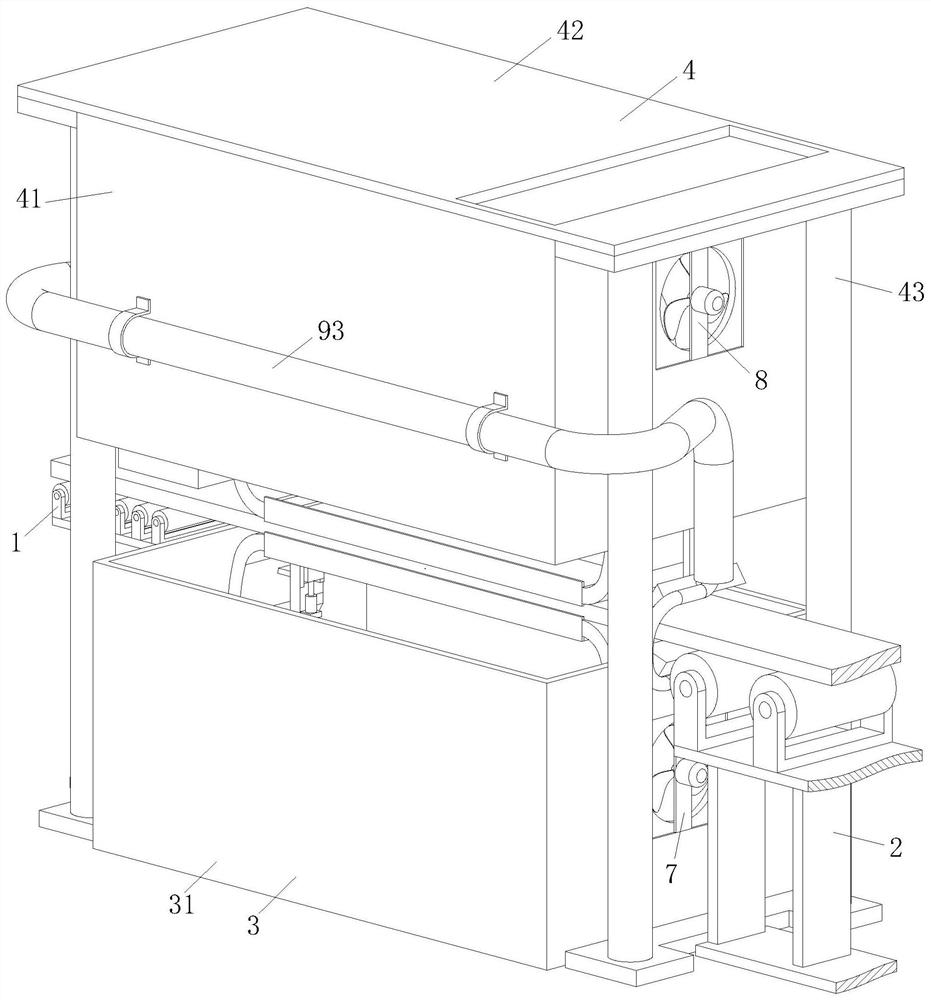
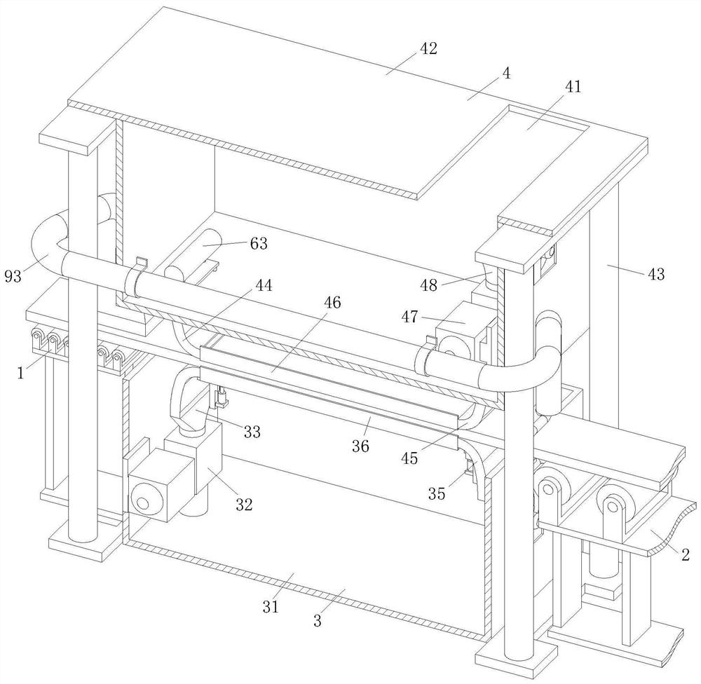
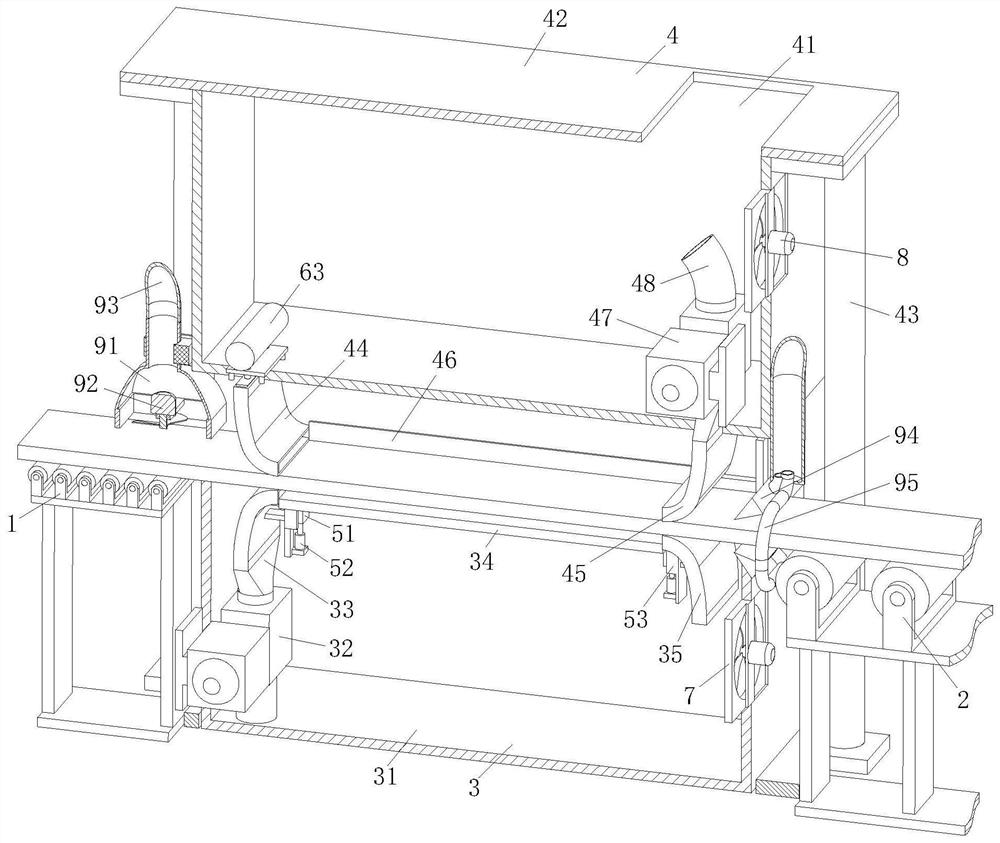
[0037] Such as Figure 1 to Figure 4 As shown, a submerged aluminum profile rapid cooling conveying device includes No. 1 rolling support part 1, No. 2 rolling support part 2, lower cooling part 3 and upper cooling part 4;

[0038] The No. 1 rolling support part 1 is set at the extrusion end of the aluminum profile forming equipment; the No. 1 rolling supporting part 1 is used to support the aluminum profile extruded by the aluminum profile forming equipment; the aluminum profile extruded by the aluminum profile forming equipment The profile is supported by the No. 1 rolling support part 1, the lower cooling part 3 and the No. 2 rolling support part 2 in sequence; the No. 2 rolling support part 2 is used to support the cooled aluminum profile; Th...


PUM


Abstract

The invention belongs to the technical field of cooling and conveying devices, and particularly relates to a rapid cooling and conveying device for an immersed aluminum profile. The device comprises arolling support part I, a rolling support part II, a lower cooling part and an upper cooling part. According to the device, cooling liquid in a cooling box body I is extracted through a water suctionpump I, and then is sprayed from an injection pipe, so as to achieve that the cooling liquid is ejected onto the lower surface of the aluminum profile, and cooling of the lower surface of the aluminum profile is achieved; at the same time, a liquid outlet pipe releases cooling liquid in a cooling box body II onto the upper surface of the aluminum profile, so as to achieve that the cooling liquidis blocked onto the aluminum profile between the liquid outlet pipe and a liquid extraction pipe through elastic sealing plates arranged on both sides, and the cooling liquid cools the upper surface of the aluminum profile; and during the process, the cooling liquid on the upper surface of aluminum alloy is constantly replaced, so as to ensure that the cooling speed of the aluminum profile is moreuniform, and the quality of the aluminum profile during the cooling process is improved.

Description

technical field [0001] The invention belongs to the technical field of cooling and conveying devices, in particular to a rapid cooling and conveying device for soaked aluminum profiles. Background technique [0002] During the processing of aluminum profiles, extrusion is the main process to form the profile. Specifically, the mold is first designed and manufactured according to the section of the profile product, and then the heated round cast rod is extruded from the mold by an extruder. However, the newly extruded aluminum profile is usually in the stage of easy deformation. In this stage of conveying and cooling, if the aluminum profile is not cooled in time to increase the strength of the aluminum profile, it will cause the aluminum profile to be deformed. Local bending deformation occurs during the transportation process, which affects the yield of aluminum profiles; [0003] Most of the aluminum profiles in the prior art are cooled by air cooling and spraying. The co...

Claims


Application Information

Patent Timeline
Patent Type & Authority Applications(China)
IPC IPC(8): B21C29/00B21C35/02
CPCB21C29/003B21C35/02
Inventor 林雪
Owner 林雪
Learn More