
Motor with internal evaporative cooling system

A technology of evaporative cooling and cooling liquid, which is applied in the direction of cooling/ventilation devices, electromechanical devices, electrical components, etc., and can solve the problems of high manufacturing cost and maintenance cost, many supporting equipment, complex structure, etc.

Pending Publication Date: 2021-05-14
大工电机(上海)有限公司
View PDF0 Cites 3 Cited by
  • Summary
  • Abstract
  • Description
  • Claims
  • Application Information

AI Technical Summary

Problems solved by technology

However, at present, the application of evaporative cooling technology in motor cooling is seldom, the main reason is that the existing technical solutions have complex structure, many supporting equipment, large volume, high manufacturing cost and maintenance cost

Method used


Image

  • Motor with internal evaporative cooling system
  • Motor with internal evaporative cooling system

Examples


Embodiment 1

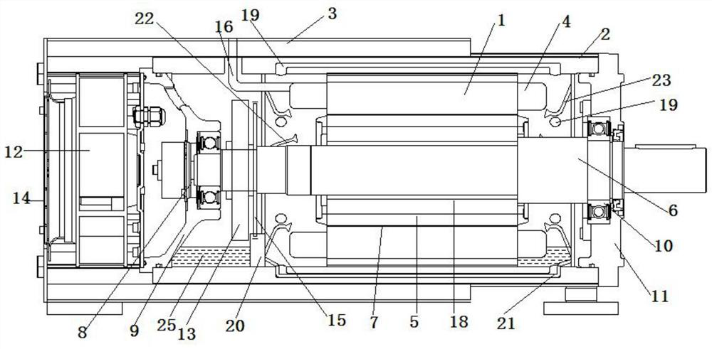
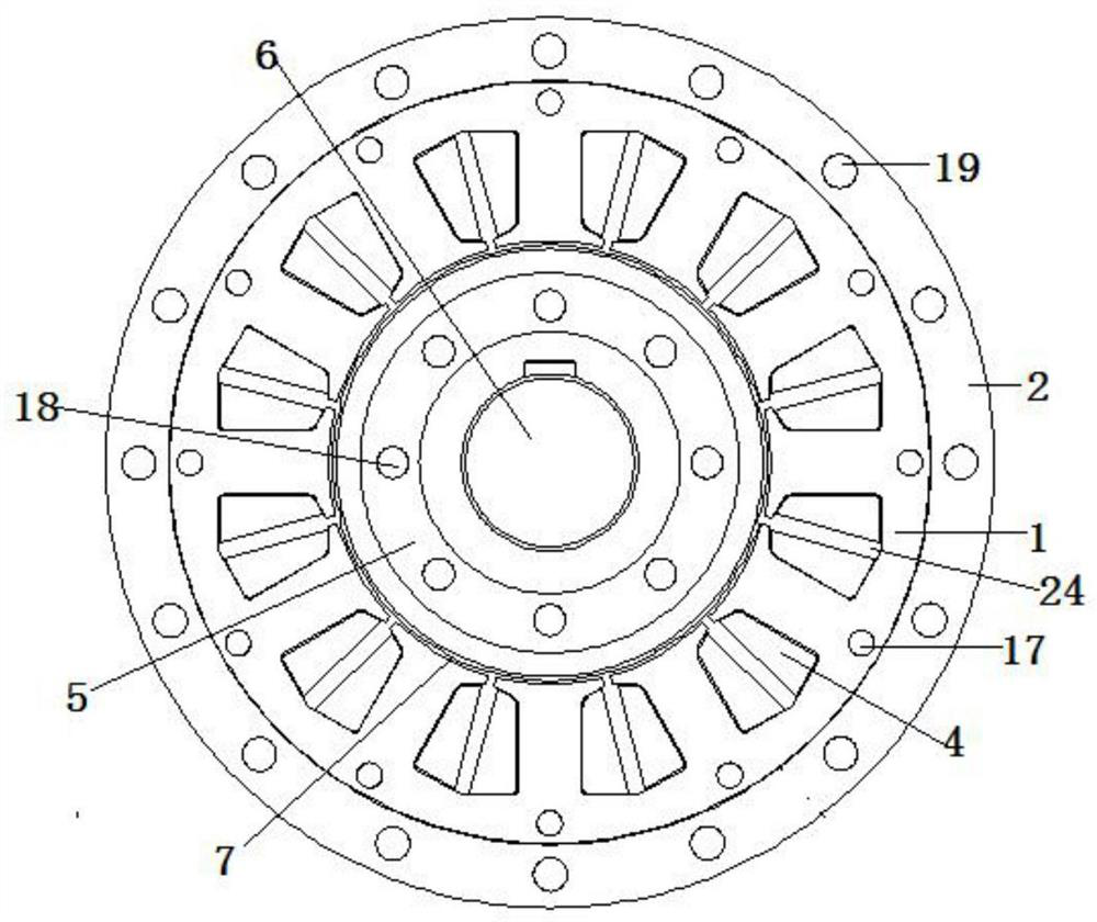
[0017]Such asfigure 1 withfigure 2A motor having an internal evaporation cooling system comprises a stator 1, the stator 1 is fixed inside the housing 2, the outer casing of the housing 2 with a cooling housing 3, and the stator 1 is inserted inside. The winding 4 is provided with a rotor 5, and the rotor 5 is attached to the rotating shaft 6, and the rotor 5 is provided with a gas gap 7 between the stator 1, the rotor 6 connects the bearing housing 8, the bearing housing 8 through The bearing bracket 9 is fixed to the inner wall of the housing 2, and the rotating shaft 6 connects the bearing seat I10, the bearing housing I10, in the right end cover 11, the right end cover 11 seals the housing 2 right end, the bearing housing 8 The motor fan 12 and the driving fan 13 are respectively provided on the left and right sides, the motor fan 12 connected to the left end cover 14, located on the left side of the bearing bracket 9, the motor fan 12 can heat the stator 1 and the rotor 5, the ...

Embodiment 2

[0019]Such asfigure 1 withfigure 2A motor having an internal evaporation cooling system comprises a stator 1, the stator 1 is fixed inside the housing 2, the outer casing of the housing 2 with a cooling housing 3, and the stator 1 is inserted inside. The winding 4 is provided with a rotor 5, and the rotor 5 is attached to the rotating shaft 6, and the rotor 5 is provided with a gas gap 7 between the stator 1, the rotor 6 connects the bearing housing 8, the bearing housing 8 through The bearing bracket 9 is fixed to the inner wall of the housing 2, and the rotating shaft 6 connects the bearing seat I10, the bearing housing I10, in the right end cover 11, the right end cover 11 seals the housing 2 right end, the bearing housing 8 The motor fan 12 and the driving fan 13 are respectively provided on the left and right sides, the motor fan 12 connected to the left end cover 14, located on the left side of the bearing bracket 9, the motor fan 12 can heat the stator 1 and the rotor 5, the ...


PUM


Abstract

The invention discloses a motor with an internal evaporative cooling system. The motor comprises a stator, the stator is fixed in a shell, a winding is embedded in a stator slot of the stator, a rotor is arranged on the inner side of the stator slot, the rotor is mounted on a rotating shaft, one end of the rotating shaft is connected with a bearing seat, and the other end of the rotating shaft is connected with a bearing seat I; the bearing seat I is fixed in the right end cover, the right end cover is connected with the right end of the shell in a sealed mode, a motor fan and a driving fan are arranged on the left side and the right side of the bearing seat respectively, the driving fan is installed on the rotating shaft, a cooling liquid driving device is installed in the shell, and a stator gaseous cooling medium channel is formed in the stator; and the rotor is provided with a rotor gaseous cooling medium channel, and the shell is provided with a shell gaseous cooling medium channel. The evaporative cooling medium of the device directly cools the interior of the motor, including a stator core, a winding wire, a rotor and a coil or magnetic steel in the rotor, so that the cooling speed is high, the cooling is uniform, and the cooling effect is good.

Description

Technical field[0001]The present invention relates to the field of motor technology, and more particularly to a motor having an internal evaporation cooling system.Background technique[0002]The motor will inevitably lose, these losses will be converted to heat, resulting in an increase in motor temperature. With the improvement of motor torque, speed and so on, the heat generated will increase significantly. If it is not possible to take heat in time, it will cause an increase in motor temperature, and the safety of the motor is harmed, and the efficiency of the motor is reduced. At the same time, the motor generally uses housing cooling mode, such as natural cooling housings, air-cooled housings, water-cooled housings, etc., heat transfer from the inside layer layer to the housing, resulting in heat dissipation, rotor and stator windings, etc. The temperature is too high. Therefore, timely, effective taking the internal heat of the motor is to ensure the safety operation of the mot...

Claims


Application Information

Patent Timeline
Patent Type & Authority Applications(China)
IPC IPC(8): H02K9/20H02K5/20H02K1/20H02K1/32H02K3/24H02K5/10
CPCH02K1/20H02K1/32H02K3/24H02K5/10H02K5/20H02K9/20
Inventor 杨东升
Owner 大工电机(上海)有限公司
Learn More