Wound surface dryer for nursing in field burn department

A dryer and wound technology, applied in physical therapy, bathing devices, etc., can solve the problems of increasing infection, difficult to heal wounds, and reducing the effect of wound treatment for patients, and achieve the effect of improving the healing effect.

Pending Publication Date: 2020-10-09
FOURTH MILITARY MEDICAL UNIVERSITY
View PDF13 Cites 0 Cited by
  • Summary
  • Abstract
  • Description
  • Claims
  • Application Information

AI Technical Summary

Problems solved by technology

[0002] The wounds of burn patients are often in a continuously moist state due to a large amount of exudation. However, according to research, the rapid sealing and healing of the wound need to keep it in a dry state; too wet a wound will increase the number of bacteria such as Pseudomonas aeruginosa and Acinetobacter baumannii. and other infection risks, making it more difficult for wounds to heal
[0003] At present, the traditional field burn department does not have a dedicated wound drying device, which reduces the treatment effect of the patient's wound. In view of the above defects, it is necessary to design a wound dryer for field burn care.

Method used


Image

  • Wound surface dryer for nursing in field burn department
  • Wound surface dryer for nursing in field burn department
  • Wound surface dryer for nursing in field burn department

Examples


Embodiment 1

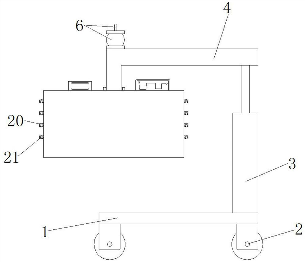
[0023] like figure 1 As shown, the wound desiccator for field burn care includes a bottom plate 1, a pulley 2, an electric push rod 3, a support rod 4, an air supply mechanism 5, an air intake mechanism 6, a support plate 7, a moving mechanism 8, a heating mechanism 9, Battery 10, connecting pipe 11, installation pipe 12, pulleys 2 are fixed at the four corners of the bottom of the bottom plate 1, an electric push rod 3 is fixed on the right side of the top of the bottom plate 1, and an electric push rod 3 is fixed on the top of the bottom plate 1. A support rod 4 is provided, the inside of the support rod 4 is fixed with an air supply mechanism 5, the left side of the top of the support rod 4 is fixed with an air intake mechanism 6, and the bottom of the support rod 4 is fixed with a support plate 7. The left and right sides of the support plate 7 are slidingly provided with a moving mechanism 8, the inner lower end of the support plate 7 is fixed with a heating mechanism 9, ...

Embodiment 2

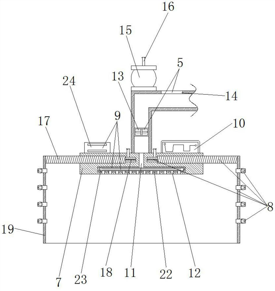
[0026] like figure 1 , figure 2 As shown, the wound desiccator for field burn care includes a bottom plate 1, a pulley 2, an electric push rod 3, a support rod 4, an air supply mechanism 5, an air intake mechanism 6, a support plate 7, a moving mechanism 8, a heating mechanism 9, Battery 10, connecting pipe 11, installation pipe 12, pulleys 2 are fixed at the four corners of the bottom of the bottom plate 1, an electric push rod 3 is fixed on the right side of the top of the bottom plate 1, and an electric push rod 3 is fixed on the top of the bottom plate 1. A support rod 4 is provided, the inside of the support rod 4 is fixed with an air supply mechanism 5, the left side of the top of the support rod 4 is fixed with an air intake mechanism 6, and the bottom of the support rod 4 is fixed with a support plate 7. The left and right sides of the support plate 7 are slidingly provided with a moving mechanism 8, the inner lower end of the support plate 7 is fixed with a heating ...


PUM


Abstract

The invention discloses a wound surface dryer for nursing in the field operation burn department. The wound surface dryer comprises a bottom plate, pulleys, an electric push rod, a supporting rod, anair supply mechanism, an air inlet mechanism, a supporting plate, a moving mechanism, a heating mechanism, a storage battery, a connecting pipe and a mounting pipe; according to the wound surface dryer for nursing in the field operation burn department, the wound surface of a patient can be located in a dry environment, so that the infection risk of pseudomonas aeruginosa, acinetobacter baumanniiand the like caused by dampness of the wound surface of the patient is prevented, and therefore, the healing effect of the wound surface of the patient is improved by using the nursing in provided bythe invention.

Description

technical field [0001] The invention relates to a wound drier, in particular to a wound drier for field burn care. Background technique [0002] The wounds of burn patients are often in a continuously moist state due to a large amount of exudation. However, according to research, the rapid sealing and healing of the wound need to keep it in a dry state; too wet a wound will increase the number of bacteria such as Pseudomonas aeruginosa and Acinetobacter baumannii. The risk of infection and so on makes the wound more difficult to heal. [0003] At present, there is no dedicated wound drying device in the traditional field burn department, which reduces the treatment effect of the patient's wound. In view of the above defects, it is necessary to design a wound dryer for nursing in the field burn department. Contents of the invention [0004] The technical problem to be solved by the present invention is to provide a wound dryer for field burn care to solve the problems rais...

Claims


Application Information

Patent Timeline
Patent Type & Authority Applications(China)
IPC IPC(8): A61H33/08
CPCA61H33/08A61H33/063A61H2201/0207A61H2201/5082
Inventor 王冬娟周琴卢迎王立娜
Owner FOURTH MILITARY MEDICAL UNIVERSITY
Why Eureka
Try Eureka