
Computer case heat dissipation hole punching device

A punching device and heat dissipation hole technology, which is applied in the direction of punching tools, forming tools, manufacturing tools, etc., can solve the problems of low punching yield, easy punching breakage, small punch spacing, etc., to ensure accuracy and Yield rate, improvement of precision and quality, effect of guaranteeing corresponding ability

Active Publication Date: 2020-10-09
浙江机电职业技术学院
View PDF6 Cites 2 Cited by
  • Summary
  • Abstract
  • Description
  • Claims
  • Application Information

AI Technical Summary

Problems solved by technology

The current heat dissipation holes are generally punched. However, when punching, because the casing of the chassis is generally relatively thin, and the current punching is generally directly punched with a punch, this leads to its When punching holes, if the punching is unfavorable, cracks are easy to appear between the punching positions, especially for the heat dissipation holes, because there are more holes at the heat dissipation holes and the spacing distance is short, when punching, the distance between the punches is small , when punching, it is easy to break between adjacent punching holes, and the problem of unevenness is prone to appear at the punching point, resulting in a low yield rate of punching, which affects the efficiency and reliability of punching

Method used


Image

  • Computer case heat dissipation hole punching device
  • Computer case heat dissipation hole punching device
  • Computer case heat dissipation hole punching device

Examples


Embodiment Construction

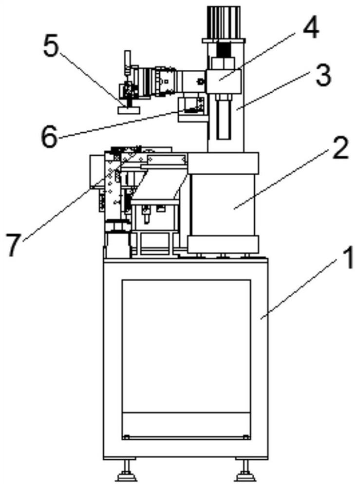
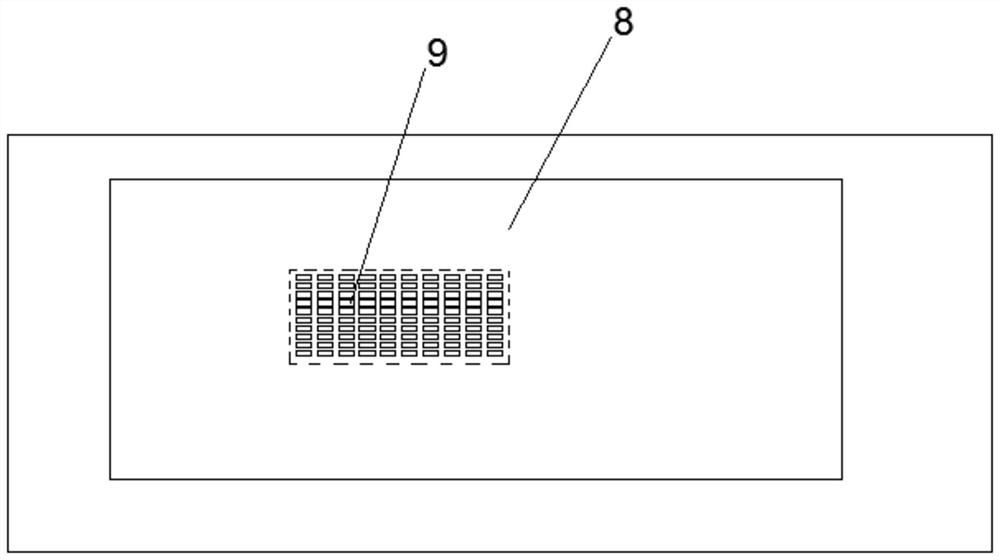
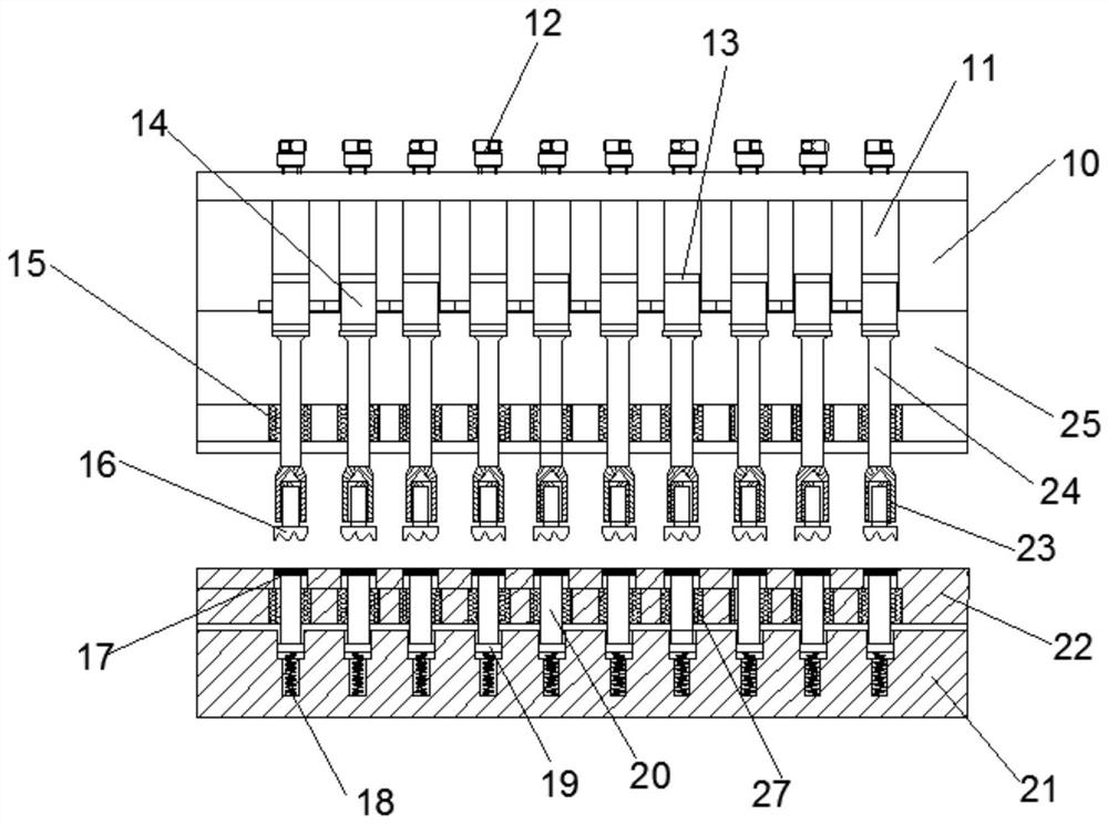
[0021] see Figure 1~4 , in an embodiment of the present invention, the computer case heat dissipation hole punching device includes a machine base 1, a machine table 2, a column 3, a driving slider 4, an auxiliary slide 6, an upper stamping die 5 and a lower stamping die 7, wherein, The top of the machine base is provided with the machine platform, one side of the machine platform is provided with a vertically extending column, and the top of the column is provided with a stamping lifting cylinder, and the column can slide up and down. The driving slider driven by the stamping lift cylinder is provided with a horizontally extending beam on the driving slider, and the auxiliary sliding seat is also provided between the beam and the side wall of the column. The beam The end of the upper stamping die 5 is provided, and the other side of the machine is provided with the lower stamping die 7 positioned below the upper stamping die. During the operation, first utilize the mutual p...


PUM


Abstract

The invention discloses a computer case heat dissipation hole punching device. The punching device is characterized in that when heat dissipation hole of a computer case are punched, the indenting operation of the heat dissipation holes of the computer case is firstly realized by utilizing the mutual press fit between an upper punching die and a lower punching die, then a punching lifting air cylinder is used for driving the upper punching die to punch the indented heat dissipation holes of the computer case, in this way, due to the fact that the indenting operation is carried out firstly, theproblems of breakage, cracks and the like occurring in the subsequent punching process can be effectively solved, the punching accuracy and yield are guaranteed, meanwhile, reclamping is not needed between indentation and punching, in this way, the accuracy of mutual correspondence of indentation and punching can be guaranteed, equipment does not need to be replaced, even a punch and an indentation head do not need to be replaced, indentation and punching operation can be completed through the same indentation head, efficiency is high, reliability is high, the corresponding capacity of indentation and punching is effectively guaranteed, and the punching precision and quality are improved.

Description

technical field [0001] The invention specifically relates to a cooling hole punching device for a computer case, and belongs to the technical field of computer accessories. Background technique [0002] For the casing of the computer, it is generally necessary to punch it before leaving the factory so as to obtain the cooling holes at the required positions. The current heat dissipation holes are generally punched. However, when punching, because the casing of the chassis is generally relatively thin, and the current punching is generally directly punched with a punch, this leads to its When punching holes, if the punching is unfavorable, cracks are likely to appear between the punching positions, especially for the heat dissipation holes, because there are more holes at the heat dissipation holes and the spacing distance is short, when punching, the distance between the punches is small , during punching, breaks are likely to occur between adjacent punching holes, and unev...

Claims


Application Information

Patent Timeline
IPC IPC(8): B21D28/26B21D28/34B21D28/00B21D22/04B21D37/10B21D35/00
CPCB21D28/26B21D28/34B21D28/002B21D22/04B21D37/10B21D35/001
Inventor 卢成浪
Owner 浙江机电职业技术学院
Learn More