
Novel fishery administration wharf boat

A fishery and pontoon technology, applied in buoys and other directions, can solve the problems of deformation and damage of the retaining plate, breaking of the retaining plate, extrusion of the retaining plate, etc., to reduce labor intensity, high safety, and good shielding effect. Effect

Inactive Publication Date: 2020-10-09
杨光
View PDF0 Cites 0 Cited by
  • Summary
  • Abstract
  • Description
  • Claims
  • Application Information

AI Technical Summary

Problems solved by technology

[0004] The purpose of the present invention is to solve the problems in the prior art that the cargo ship will sway up and down when unloading. Since it is floating in the water, its swing position is relatively large, which is easy to squeeze the material retaining steel plate, and even cause the material retaining steel plate to sway. The shortcoming is that the barge is turned up and broken by extrusion or the plate seat is broken. During the unloading process, the height difference between the barge and the cargo ship gradually increases, and when it swings up and down, it will cause strong extrusion to the retaining steel plate and cause it to be deformed and damaged. A new type of fishery barge

Method used


Image

  • Novel fishery administration wharf boat
  • Novel fishery administration wharf boat

Examples


Embodiment 1

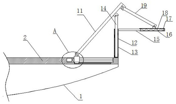
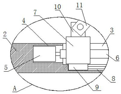
[0020] refer to Figure 1-2 , a new type of fishery pontoon, comprising a hull 1, a deck 2 is provided on the hull 1, a transmission slot 3 is provided on the top of the deck 2, a motor slot 4 is provided on the inner wall of one side of the transmission slot 3, and a motor slot 4 is provided on one side of the motor slot 4 A rotating motor 5 is fixedly installed on the inner wall, and a screw rod 6 is fixedly installed on the output shaft of the rotating motor 5. The screw rod 6 is threadedly connected with a threaded seat 7, and the bottom of the threaded seat 7 is fixedly installed with a square horizontal block 9 and a transmission groove 3 A square chute 8 is provided on the bottom inner wall of the square chute 8, and the bottom of the square horizontal block 9 extends into the square chute 8, and the same horizontal bar is fixedly installed on the inner walls of both sides of the square chute 8, and the square horizontal block 9 is slidably installed on the On the horiz...

Embodiment 2

[0027] refer to Figure 1-2 , a new type of fishery pontoon, comprising a hull 1, a deck 2 is provided on the hull 1, a transmission slot 3 is provided on the top of the deck 2, a motor slot 4 is provided on the inner wall of one side of the transmission slot 3, and a motor slot 4 is provided on one side of the motor slot 4 A rotating motor 5 is fixedly installed on the inner wall, and a screw rod 6 is fixedly installed on the output shaft of the rotating motor 5. The screw rod 6 is threadedly connected with a threaded seat 7, and the bottom of the threaded seat 7 is fixedly installed with a square horizontal block 9 and a transmission groove 3 A square chute 8 is provided on the bottom inner wall of the square chute 8, and the bottom of the square horizontal block 9 extends into the square chute 8, and the same horizontal bar is fixedly installed on the inner walls of both sides of the square chute 8, and the square horizontal block 9 is slidably installed on the On the horiz...


PUM


Abstract

The invention discloses a novel fishery administration wharf boat. The boat comprises a hull, a deck is arranged on the hull; a transmission groove is formed in the top of the deck; a motor groove isformed in the inner wall of one side of the transmission groove; a rotating motor is fixedly mounted on the inner wall of one side of the motor groove; a screw rod is fixedly mounted on an output shaft of the rotating motor; the screw rod is in threaded connection with a threaded seat; a square horizontal block is fixedly mounted at the bottom of the threaded seat; a square sliding groove is formed in the inner wall of the bottom of the transmission groove, the bottom of the square horizontal block extends into the square sliding groove, the same horizontal rod is fixedly installed on the inner walls of the two sides of the square sliding groove, the square horizontal block is installed on the horizontal rod in a sliding mode, and the top of the threaded base extends to the position abovethe deck and is fixedly provided with a rotating block. The boat has the advantages of being simple in structure, convenient to use, capable of adjusting the using angles of the material blocking plate and the material guiding plate, good in blocking effect, capable of reducing the labor intensity of workers, high in safety and the like.

Description

technical field [0001] The invention relates to the technical field of barges, in particular to a novel fishery administration barge. Background technique [0002] A barge is a rectangular flat-bottomed boat without a power device, usually fixed on the shore, and generally used as a floating dock for loading and unloading goods or for pedestrians to get on and off. When loading and unloading cargo, the incoming cargo ship from the raw material wharf docks beside the barge. Due to the need for protection, a certain gap is required between the two. As the river floats, the size of the gap will continue to change. [0003] At present, in order to prevent cargo damage caused by unloading spilled materials, the steel plate is installed on the barge through hinges, and then placed between the cargo ship and the barge as a material retaining device. Although it has a certain effect, many shortcomings have been found in the process of use , the cargo ship will sway up and down when...

Claims


Application Information

Patent Timeline
IPC IPC(8): B63B35/34
CPCB63B35/34
Inventor 杨光
Owner 杨光
Learn More