A waste thermal cracking gasifier
A thermal cracking and gasifier technology, which is applied in the gasification process, the production of combustible gas, and the combination of fuel pre-dry distillation, etc., can solve the problem that the thermal cracking gasifier cannot be disassembled and assembled quickly, and achieves reduction of manual operation intensity and savings. time, the effect of reducing the number of feeds
- Summary
- Abstract
- Description
- Claims
- Application Information
AI Technical Summary
Problems solved by technology
Method used
Image
Examples
specific Embodiment approach 1
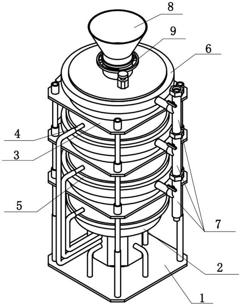
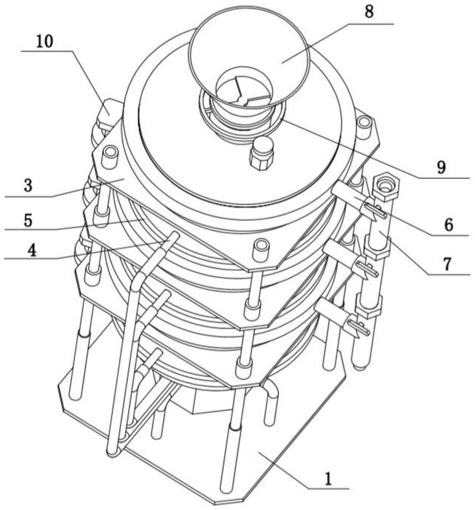
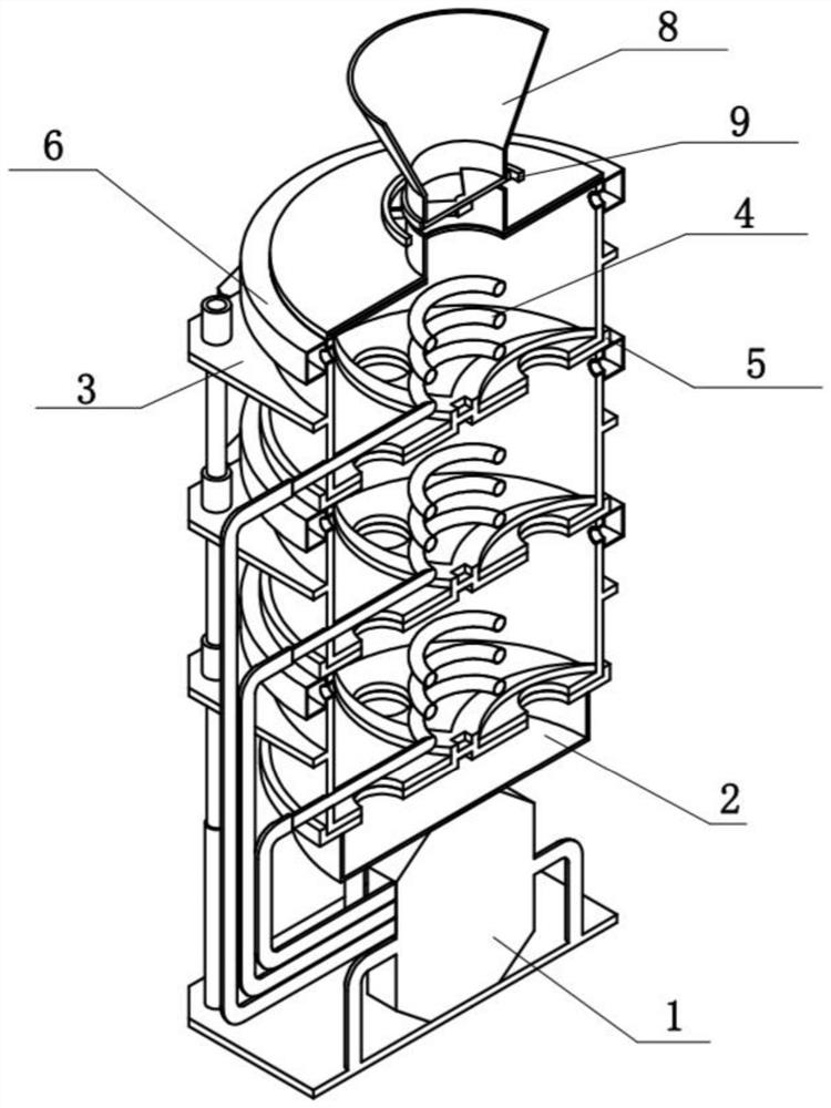
[0035] Bonded below Figure 1-12In the present embodiment, a waste thermal cracking gasifier comprising a high temperature heating assembly 1, an ash case 2, a reaction outer frame assembly 3, a heating assembly 4, a sheet assembly 5, an air assembly 6, a guide assembly 7, a storage assembly 8, the feed assembly 9 and the driving assembly 10, the ash case 2 detachably connected to the high temperature heating assembly 1, the high temperature heating assembly 1 has a plurality of high temperature heating assemblies 1, sequentially detachable connection, the lowermost high temperature The heating assembly 1 is fixed to the high temperature heating assembly 1, and the middle portion of the plurality of reaction outer frame assemblies 3 is provided with a heating assembly 4, and the lower end of the plurality of reaction outer frame assemblies 3 is rotated to be connected to the sheet assembly 5, and multiple reactions. The upper end of the frame assembly 3 is fixedly connected to the ...
specific Embodiment approach 2
[0038] Bonded below Figure 1-12 In the present embodiment, the high temperature heating assembly 1 includes a high temperature bottom plate 1-1, a fast-mounted column 1-2, a high temperature heater 1-3, and a hierarchical heat transfer tube 1-4, and four angles at high temperature base plates 1-1. Fast connection is fixed to the quick-load column 1-2, and the high temperature heater 1-3 is fixed to the high temperature bottom plate 1-1, and the plurality of hierarchical thermally conductive tubes 1-4 are fixed to the front side of the high temperature heater 1-3; high temperature heating 1-3 can provide different temperatures for multiple hierarchical thermal tubes 1-4, the highest level of grading thermal tube 1-4 temperature at 200-600 degrees Celsius, the hierarchical thermal tube 1-4 temperature at 600-1200 degrees Celsius The minimum hierarchical thermal tube 1-4 temperature is 600-800 degrees Celsius, which provides different temperatures for drying, pyrolysis and oxidation ...
specific Embodiment approach 3
[0040] Bonded below Figure 1-12 In the present embodiment, the reaction outer frame assembly 3 includes a reaction outer frame plate 3-1, a quick-loading insertion column 3-2, a fast-mounted positioning post 3-3, a reaction barrel 3-4, a gas outflow hole 3-5 , High temperature mounting holes 3-6, reaction bottom plates 3-7 and the lower bore 3-8, the four angles at the lower end of the lower end of the reaction outer frame 3-2 are rotated in the pillar 3-2, the reaction outside the box The four angles at the upper end of the plate 3-1 are fixedly connected to the quick-loaded positioning post 3-3, and the reaction barrel 3-4 is fixedly connected to the reaction outer frame 3-1, and there are a plurality of upper ends of the reaction barrels 3-4. The gas flow outlet 3-5, the lower portion of the reaction tub 3-4 is provided with a high temperature mounting hole 3-6, and the reaction bottom plate 3-7 is fixedly attached to the lower end of the reaction barrel 3-4, and there are a pl...
PUM
 Abstract
Description
Claims
Application Information
 - R&D
- Intellectual Property
- Life Sciences
- Materials
- Tech Scout
- Unparalleled Data Quality
- Higher Quality Content
- 60% Fewer Hallucinations
Browse by: Latest US Patents, China's latest patents, Technical Efficacy Thesaurus, Application Domain, Technology Topic, Popular Technical Reports.
© 2025 PatSnap. All rights reserved.Legal|Privacy policy|Modern Slavery Act Transparency Statement|Sitemap|About US| Contact US: help@patsnap.com


