Cloth cutting device for garment processing

A cutting device, cloth technology, applied in the cutting of textile materials, textiles and papermaking, etc.

Active Publication Date: 2020-10-09
东莞市珠峰信息科技有限公司
View PDF5 Cites 6 Cited by
  • Summary
  • Abstract
  • Description
  • Claims
  • Application Information

AI Technical Summary

Problems solved by technology

[0005] In order to overcome the disadvantage of manually holding scissors to cut cloth, the technical problem to be solved by the present invention is to provide a cloth cutting device for garment processing that can cut cloth evenly, save time and effort, and improve cutting efficiency

Method used


Image

  • Cloth cutting device for garment processing
  • Cloth cutting device for garment processing
  • Cloth cutting device for garment processing

Examples


Embodiment 1

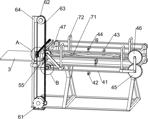
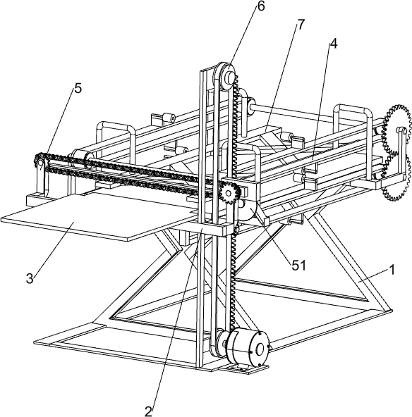
[0022] A cloth cutting device for garment processing, such as Figure 1-5 As shown, it includes a base 1, a mounting frame 2, a material placing plate 3, a material shifting mechanism 4 and a cutting mechanism 5, the upper left side of the base 1 is connected with a mounting frame 2, and the top of the mounting frame 2 is connected with a material setting plate 3 in the middle A cutting mechanism 5 is installed on the right side of the mounting frame 2, and a material shifting mechanism 4 is installed between the inner surfaces of the base 1 top.

[0023] The material shifting mechanism 4 includes a first conveyor belt 41, a first clamping rod 42, a second conveyor belt 43, a second clamping rod 44, a first gear 45, a second gear 46, a transmission shaft 47 and a third gear 48, and the base 1. Two drive shafts 47 are rotatably connected between the inner surface of the upper left side, and the two drive shafts 47 on the left are symmetrical up and down. Two drive shafts 47 are...

Embodiment 2

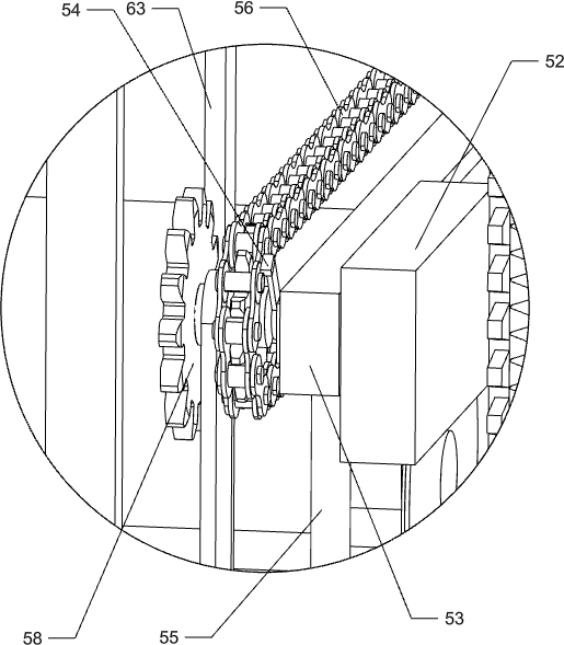
[0027] On the basis of Example 1, such as Figure 1-5 As shown, a linkage mechanism 6 is also included, and the linkage mechanism 6 includes a servo motor 61, a pulley 62, a rack belt 63 and a fixed frame 64, the bottom left side of the base 1 is equipped with a servo motor 61, and the output shaft of the servo motor 61 passes through The shaft coupling is connected with a pulley 62, and the top of the mounting frame 2 on the front side of the material plate 3 is connected with a fixed mount 64, and the fixed mount 64 is also connected with a pulley 62 in a rotating manner, and a rack belt 63 is connected between the two pulleys 62. The rack belt 63 meshes with the third gear 48 , and the rack belt 63 also meshes with the fourth gear 58 .

[0028] Initially, the rack belt 63 meshes with the third gear 48, and the servo motor 61 is manually activated to make the pulley 62 on it rotate counterclockwise. The counterclockwise rotation of the pulley 62 drives the rack belt 63 to ro...


PUM


Abstract

The invention relates to a cutting device, in particular to a cloth cutting device for garment processing. The technical problem to be solved by the invention is how to provide the cloth cutting device for garment processing, which is capable of uniformly cutting cloth, saving time and labor and improving the cutting efficiency. In order to above the technical problem, the invention provides a cloth cutting device for garment processing; the cutting device comprises a base, a material placing plate, a cutting mechanism, and a material moving mechanism, wherein the mounting frame is connected to one side of the upper portion of the base; the material placing plate is connected to the end part of the mounting frame; the cutting mechanism is arranged at one side of the mounting frame; and thematerial moving mechanism is arranged between the inner side surface at the upper portion of the base. The cloth can be clamped through mutual cooperation of a first material clamping rod and a second material clamping rod, a first conveyor belt rotates clockwise, a second conveyor belt rotates counter-clockwise, the cloth can be pulled out through the cooperation of the first material clamping rod and the first material clamping rod, and a cutting machine moves backward to cut the cloth.

Description

technical field [0001] The invention relates to a cutting device, in particular to a cloth cutting device for garment processing. Background technique [0002] The initial fabrics produced by fabric factories are generally long, and garment processing factories generally need to cut long fabrics into pieces of short fabrics in order to facilitate the production of long fabrics into garments. When cutting the fabric manually, the fabric needs to be pulled out to an appropriate length first, and then cut with scissors, which is time-consuming and laborious, and the cutting efficiency is relatively low, and manually holding the scissors to cut the fabric by feeling, It is more difficult to get a consistent cut in the fabric, which can result in uneven cuts in the fabric, which can result in uneven cuts in the fabric. [0003] Therefore, it is necessary to develop a cloth cutting device for garment processing that can evenly cut cloth, save time and effort, and improve cutting ...

Claims


Application Information

Patent Timeline
Patent Type & Authority Applications(China)
IPC IPC(8): D06H7/00
CPCD06H7/00
Inventor 肖祥燕
Owner 东莞市珠峰信息科技有限公司
Why Eureka
Try Eureka