Movable cast-in-place beam side formwork device and using method thereof

A cast-in-place beam and mobile technology, which is applied in bridges, bridge construction, erection/assembly of bridges, etc., can solve problems such as high safety risks in hoisting operations, expensive supporting equipment, and self-heavy formwork, so as to achieve a simple and feasible combined structure, Easy to install and disassemble, to ensure the effect of pouring quality

Pending Publication Date: 2020-10-09
CHINA RAILWAY SHANGHAI ENGINEERING BUREAU GROUP CO LTD +1
View PDF0 Cites 0 Cited by
  • Summary
  • Abstract
  • Description
  • Claims
  • Application Information

AI Technical Summary

Problems solved by technology

[0002] At present, most of the steel side forms used in domestic cast-in-place construction bridges are single-piece assembled formwork. When one span beam is completed and the next span beam is constructed, the single formwork needs to be disassembled and transferred, and the crane and transport vehicles need to wait for a long time to cooperate. , which consumes a lot of machinery and shifts, and has low work efficiency. Especially when there are municipal roads under the bridge, it will also hinder the passage of social vehicles, resulting in a long construction period for each bridge poured on site, a large safety risk in hoisting operations, and a great impact on traffic.
[0003] For the integral formwork, the applicability of the integral formwork is poor when the spans of the cast-in-place beams are different; and when the spans are large, the formwork is self-heavy and requires high support systems; Type formwork and supporting equipment are expensive, and ordinary projects are unaffordable. In addition, when the integral formwork moves, the bottom form needs to be moved at the same time, which also greatly increases the construction period of single-span cast-in-place beams and the turnaround time of formwork.

Method used


Image

  • Movable cast-in-place beam side formwork device and using method thereof
  • Movable cast-in-place beam side formwork device and using method thereof
  • Movable cast-in-place beam side formwork device and using method thereof

Examples


Embodiment 1

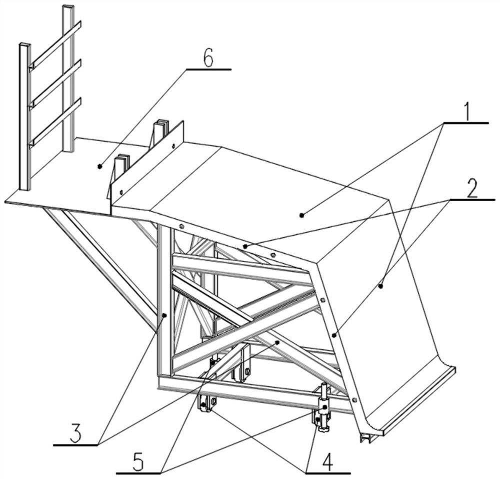
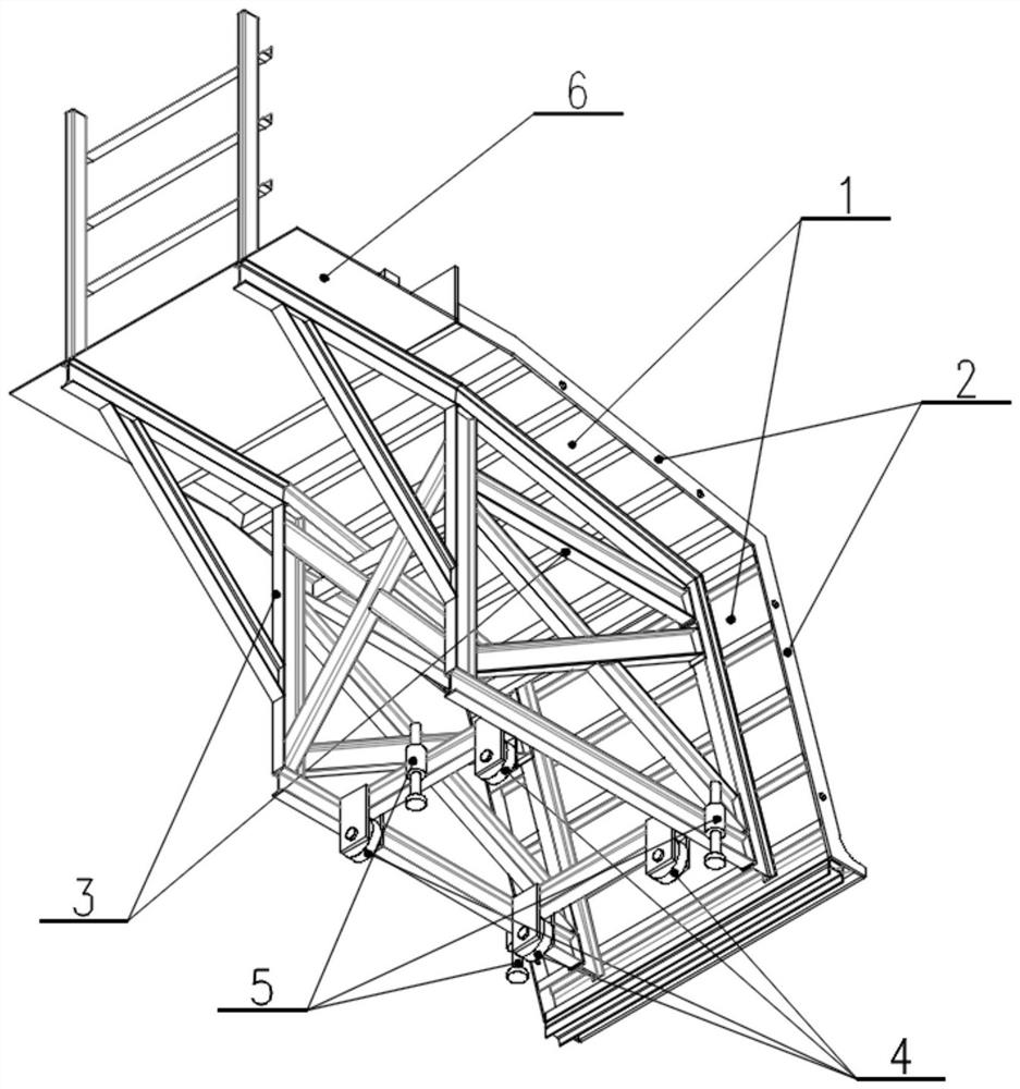
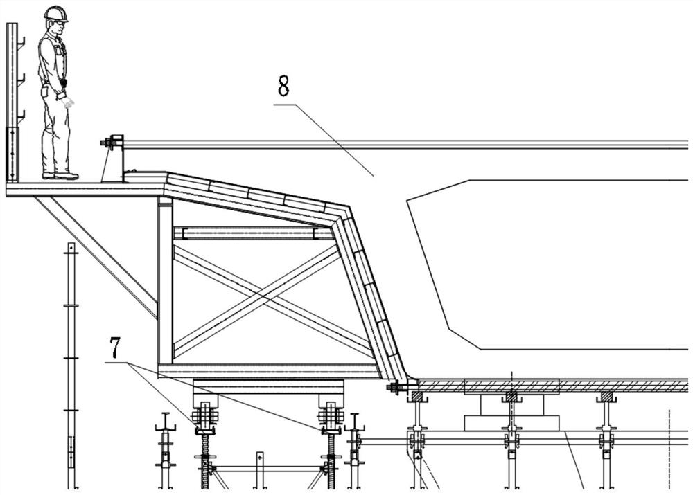
[0033] combine image 3 As shown, when in use, after the support and channel steel track are erected, the mobile cast-in-place beam side form is hoisted from the beam end to the support, and the running wheels are dropped into the channel steel track to pair the formwork units It is arranged on both sides of the cast-in-place beam, and the number of formwork units is determined according to the length of a single pouring.

[0034] Then, the formwork units are manually pushed to the predetermined position one by one, so that two adjacent formworks are close together, and wooden wedges are inserted under the running wheels to fix them. After the formwork unit is in place, pass the bolts through the two outer ribs on the back of the work plate to connect the formwork unit as a whole. If necessary, use jacks and other tools to fine-tune the horizontal position of the formwork.

[0035] Then, adjust the jacking screws of each formwork unit in turn to make the horizontal inclinatio...


PUM


Abstract

The invention relates to the technical field of cast-in-place beams, and particularly relates to a movable cast-in-place beam side formwork device and a using method thereof. The surface of a workingplate is similar to the side face of a cast-in-place beam, the end, away from the cast-in-place beam, of the working plate extends upwards, and a matching hole is formed in the position, higher than the beam face of the cast-in-place beam, of the working plate in the direction close to the cast-in-place beam; a supporting truss is arranged at the bottom of the working plate and used for supportingthe working plate, and walking wheels and an adjusting jacking are arranged at the bottom of the supporting truss. Compared with the prior art, the device provided by the invention has the advantagesthat the working plate matches the two sides of the cast-in-place beam and is connected with the cast-in-place beam through split bolts, so that the pouring quality is guaranteed, and hoisting is facilitated; the adopted modular unit design is suitable for cast-in-place beam construction of various spans, and the applicability is high; the adjusting jacking is arranged, so that the height of a formwork is convenient to adjust; and by adopting a roller sliding design and matching the walking wheels with a channel steel rail, the formwork is very convenient to turn over and transfer.

Description

technical field [0001] The invention relates to the technical field of cast-in-place beams, in particular to a mobile cast-in-place beam side form device. Background technique [0002] At present, most of the steel side forms used in domestic cast-in-place construction bridges are single-piece assembled formwork. When one span beam is completed and the next span beam is constructed, the single formwork needs to be disassembled and transferred, and cranes and transport vehicles need to wait for a long time to cooperate. , It consumes many machines and shifts, and the work efficiency is low. Especially when there is a municipal road under the bridge, it will also hinder the passage of social vehicles, resulting in a long construction period for each bridge poured on site, a large safety risk in hoisting operations, and a great impact on traffic. [0003] For the integral formwork, the applicability of the integral formwork is poor when the spans of cast-in-place beams are diff...

Claims


Application Information

Patent Timeline
Patent Type & Authority Applications(China)
IPC IPC(8): E01D21/00
CPCE01D21/00
Inventor 刘习生郑峰立刘绩徐明发边海洋张永晓王保凤
Owner CHINA RAILWAY SHANGHAI ENGINEERING BUREAU GROUP CO LTD
Why Eureka
Try Eureka