
Vehicle light guide tail structure and vehicle light guide

A light guide and vehicle technology, applied in the field of vehicle light guide tail structure, can solve the problems of reducing the light-emitting length of the light guide, limiting the sense of the light line, and the bright spots cannot be blocked, etc., to optimize the lighting uniformity, eliminate bright spots, and eliminate bright spot defects Effect

Pending Publication Date: 2020-10-09
HASCO VISION TECHNOLOGY CO LTD
View PDF0 Cites 0 Cited by
  • Summary
  • Abstract
  • Description
  • Claims
  • Application Information

AI Technical Summary

Problems solved by technology

[0003] As a light-emitting technology, light guides have total reflection of light at the end of the light guide due to their own luminous characteristics, which is reflected in the appearance of the lamps. The defect of the tail bright spot is difficult to meet the lighting uniformity requirements of the lamps.
[0004] In the prior art, a light-shielding structure is generally used on the decorative ring to solve this problem. When assembling with the light guide, the light-shielding structure is directly assembled with the tail of the light guide to cover the tail of the light guide. However, this solution has limitations. On the one hand, due to occlusion, the light-emitting length of the light guide is reduced, which limits the line sense of the light guide; on the other hand, the problem cannot be solved fundamentally. Although the bright spots are blocked from the perspective of the front of the car, but from the perspective of both sides of the car , the bright spots cannot be blocked, and still cannot solve the problem of bright spots at the end of the light guide

Method used


Image

  • Vehicle light guide tail structure and vehicle light guide
  • Vehicle light guide tail structure and vehicle light guide
  • Vehicle light guide tail structure and vehicle light guide

Examples


Embodiment Construction

[0022] The present invention will be further described below in conjunction with the accompanying drawings and specific embodiments.

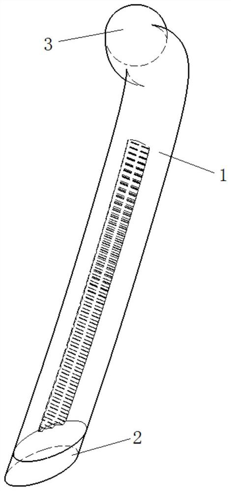
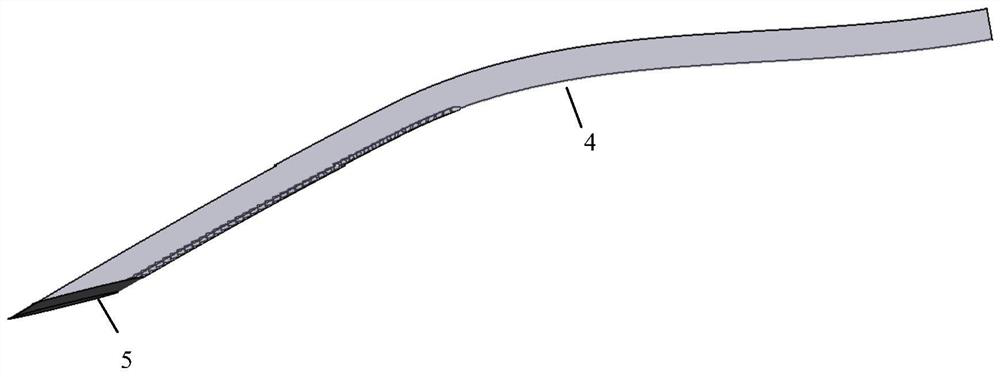
[0023] see Figure 1-Figure 4 , a light guide tail structure for vehicles, comprising a long light guide body 1, the end of the light guide body 1 away from the light source has a light guide tail 2 connected with the light guide body 1 by two-color injection molding; the light guide tail 2. Light absorbing materials or discrete materials with good scattering properties are used; the light guide tail 2 has a thickness of 1-5 mm.

[0024] In this embodiment, as a further preference, the thickness of the light guide tail part 2 is 2mm, and the tolerance is 10%.

[0025] In this example, if image 3 As shown, the light guide tail 2 is made of black injection molding material 5 , and it is a better solution to choose black injection molding material 5 . by image 3 For example: the main body of the light guide is made of LC1500 transparent mate...


PUM

PropertyMeasurementUnit
Thicknessaaaaaaaaaa
Thicknessaaaaaaaaaa

Abstract

The invention relates to a vehicle light guide tail structure. The vehicle light guide tail structure comprises a long-strip-shaped light guide body, the end, away from a light source, of the light guide body is provided with a light guide tail connected with the light guide body into a whole in a double-color injection molding mode, the light guide tail is made of a light absorption material or adiscrete material with good scattering performance, and the thickness of the light guide tail is 1-5 mm. A double-color injection molding process is adopted, a transparent material is replaced with amaterial with low transmittance and good absorption performance or a discrete material with good scattering performance in a material thickness area with a certain thickness at the light guide tail,so that bright spots at the light guide tail are eliminated, and meanwhile, the light guide is prevented from emitting less light and limiting the line feeling of the light guide due to a traditionaldecorative ring shielding scheme.

Description

technical field [0001] The invention relates to a light guide for vehicle lamps, in particular to a rear structure of a light guide for vehicles, belonging to the technical field of light guides for vehicles. Background technique [0002] Due to the advantages of environmental protection and energy saving, high efficiency and longevity, and pure luminous color, LED light sources have been widely used in automotive lamps. With the development of LED application technology, light guide technology came into being. The outer diameter of light guide is usually between 5mm-10mm. The space utilization of lamps is more reasonable. Bold, casual, family-oriented design concept. [0003] As a light-emitting technology, light guides have total reflection of light at the tail of the light guide due to their own light-emitting characteristics, which is reflected in the appearance of the lamps and will produce defects in the tail bright spots, making it difficult to meet the lighting unif...

Claims


Application Information

Patent Timeline
IPC IPC(8): F21S41/24F21S43/236F21W107/10F21Y115/10
CPCF21Y2115/10F21S41/24F21S43/236F21W2107/10
Inventor 吴刚胡尚斌余军秦羊阳何钊英
Owner HASCO VISION TECHNOLOGY CO LTD
Learn More