
Optical system capable of eliminating central bright spot and method for adjusting light divergence angle

An optical system and bright spot technology, which is applied in the field of optics, can solve the problems of the unfavorable influence of special-shaped light fields, the inability to eliminate the zero-order diffraction center bright spot of diffractive optical elements, etc., and achieve low cost, simple and convenient adjustment of light divergence angle, and miniaturized size Effect

Active Publication Date: 2018-09-11
JIAXING UPHOTON OPTOELECTRONICS TECH CO LTD
View PDF4 Cites 0 Cited by
  • Summary
  • Abstract
  • Description
  • Claims
  • Application Information

AI Technical Summary

Problems solved by technology

[0008] However, if only the diffractive optical element is used to design the special-shaped light field, the central bright spot of the zero-order diffraction produced by the diffractive optical element cannot be eliminated. For some special application fields, the central bright spot will have an adverse effect on the application of the special-shaped light field.

Method used


Image

  • Optical system capable of eliminating central bright spot and method for adjusting light divergence angle
  • Optical system capable of eliminating central bright spot and method for adjusting light divergence angle
  • Optical system capable of eliminating central bright spot and method for adjusting light divergence angle

Examples


Embodiment 1

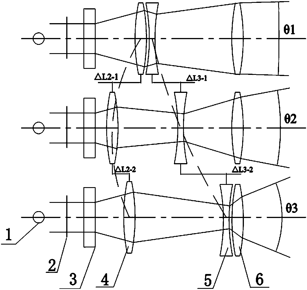
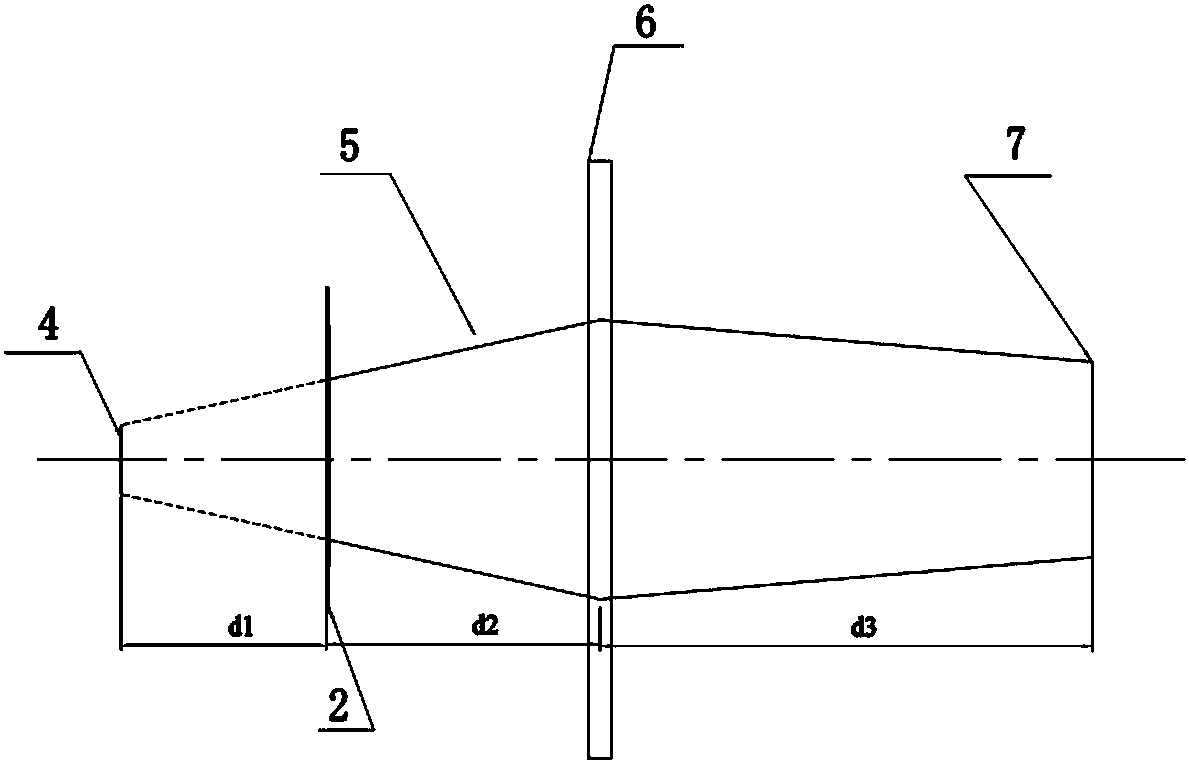
[0036] Such as Figure 4 and 5As shown, the illuminating light source 1 is a collimated light illuminating light source, and the diffractive optical structure 2 cooperates with the imaging lens through the diffractive optical element designed as a virtual image. According to the system design requirements, the collimated light illuminating light source is used to realize the special-shaped light field. The diffractive optical structure 2 in the present invention can be designed as a Fresnel diffractive optical element or a Fraunhofer diffractive optical element. The diffractive optical element is irradiated by parallel light, and its light field divergence angle is θ0. Place the refraction optical structure 2 between the illumination light source 1 and the zoom lens structure 3, the distance between the special-shaped light field position 6 realized by the refraction optical structure 2 and the main section position 7 of the zoom lens structure of the imaging system is U1, and...

Embodiment 2

[0038] Such as Figure 4 and 6 As shown, the illuminating light source 1 is a collimated light illuminating light source, and the diffractive optical structure 2 cooperates with the imaging lens through the diffractive optical element designed as a virtual image. According to the system design requirements, the collimated light illuminating light source is used to realize the special-shaped light field. The diffractive optical structure 2 in the present invention can be designed as a Fresnel diffractive optical element or a Fraunhofer diffractive optical element. The diffractive optical element is irradiated by parallel light, and its light field divergence angle is θ0. Place the refraction optical structure 2 between the illumination light source 1 and the zoom lens structure 3, the distance between the special-shaped light field position 6 realized by the refraction optical structure 2 and the main section 7 of the zoom lens structure of the imaging system is U2, and the ima...

Embodiment 3

[0040] Such as Figure 4 and 7 As shown, the illuminating light source 1 is a collimated light illuminating light source, and the diffractive optical structure 2 cooperates with the imaging lens through the diffractive optical element designed as a virtual image. According to the system design requirements, the collimated light illuminating light source is used to realize the special-shaped light field. The diffractive optical structure 2 in the present invention can be designed as a Fresnel diffractive optical element or a Fraunhofer diffractive optical element. The diffractive optical element is irradiated by parallel light, and its light field divergence angle is θ0. Place the refraction optical structure 2 between the illumination light source 1 and the zoom lens structure 3, the distance between the special-shaped light field position 6 realized by the refraction optical structure 2 and the main section position 7 of the zoom lens of the imaging system is U3, and the imag...


PUM


Abstract

The invention discloses an optical system capable of eliminating central light spots, which comprises a refractive-diffractive optical structure, a collimating irradiation light source and a zoom lens structure, and is characterized in that the refractive-diffractive optical structure comprises a virtual image design diffractive optical element and an imaging lens, and a central cross section of the refractive-diffractive optical structure is a principal cross section of the imaging lens; the refractive-diffractive optical structure is placed between the collimating irradiation light source and the zoom lens structure, and is used for realizing optical field distribution required by the optical system; and the virtual image design diffractive optical element is located between the collimating irradiation light source and the imaging lens. According to the invention, the refractive-diffractive optical structure is adopted to be matched with the zoom lens structure, the collimating irradiation light source and the virtual image design diffractive optical element are fixed in operation, illumination divergence angle regulation of the required optical field can be realized through regulating the zoom lens structure, and influences of the central light spots of zero-order diffraction are completely eliminated at the same time. In addition, the optical system disclosed by the invention is concise in optical structure, simple and convenient in illumination divergence angle regulation, high in optical efficiency, miniaturized in size, low in cost and easy to operate.

Description

technical field [0001] The invention belongs to the field of optics, and in particular relates to an optical system capable of eliminating central bright spots and a method for adjusting the divergence angle of illumination thereof. Background technique [0002] In modern technology, with the application and development of optoelectronic equipment and systems, the application of special-shaped laser light fields with adjustable divergence angles in various optoelectronic product fields is becoming more and more extensive, and the requirements for special-shaped laser light fields with adjustable divergence angles are also increasing. , based on the development of diffractive optics and laser technology, it has been possible to realize special-shaped laser light fields with fixed divergence angles, such as gun sight light fields, ring light fields, grid light fields and other laser tool light fields, but if the special-shaped light field divergence The adjustment of the angle...

Claims


Application Information

Patent Timeline
Patent Type & Authority Patents(China)
IPC IPC(8): G02B27/42G02B27/09
CPCG02B27/0944G02B27/095G02B27/4233
Inventor 田克汉尹晓东霍轶杰潘卫清贲宇
Owner JIAXING UPHOTON OPTOELECTRONICS TECH CO LTD
Learn More