
An impact test device and experimental method based on a space-moving sandwich plate structure

A technology of space movement and impact testing, which is applied in the testing of machines/structural components, impact testing, measuring devices, etc., can solve problems such as simulation of impact response behavior tests of composite sandwich panels, and achieve convenient and rapid installation and combination replacement, and realize The effect of synchronicity

Active Publication Date: 2021-09-17
HARBIN ENG UNIV
View PDF0 Cites 0 Cited by
  • Summary
  • Abstract
  • Description
  • Claims
  • Application Information

AI Technical Summary

Problems solved by technology

[0004] In order to solve the impact test of the existing fixing device, the present invention has the problem that it cannot be used for the test simulation of the impact response behavior of the composite sandwich plate structure in a moving state

Method used


Image

  • An impact test device and experimental method based on a space-moving sandwich plate structure
  • An impact test device and experimental method based on a space-moving sandwich plate structure
  • An impact test device and experimental method based on a space-moving sandwich plate structure

Examples


specific Embodiment approach 1

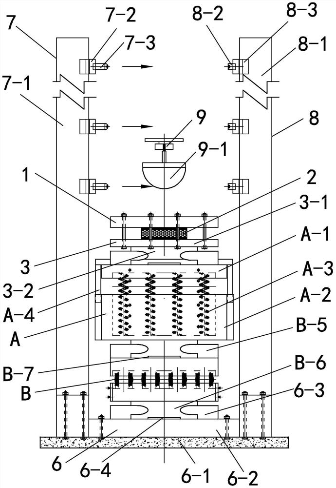
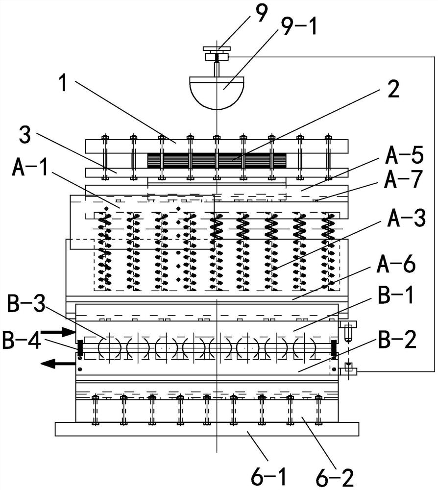
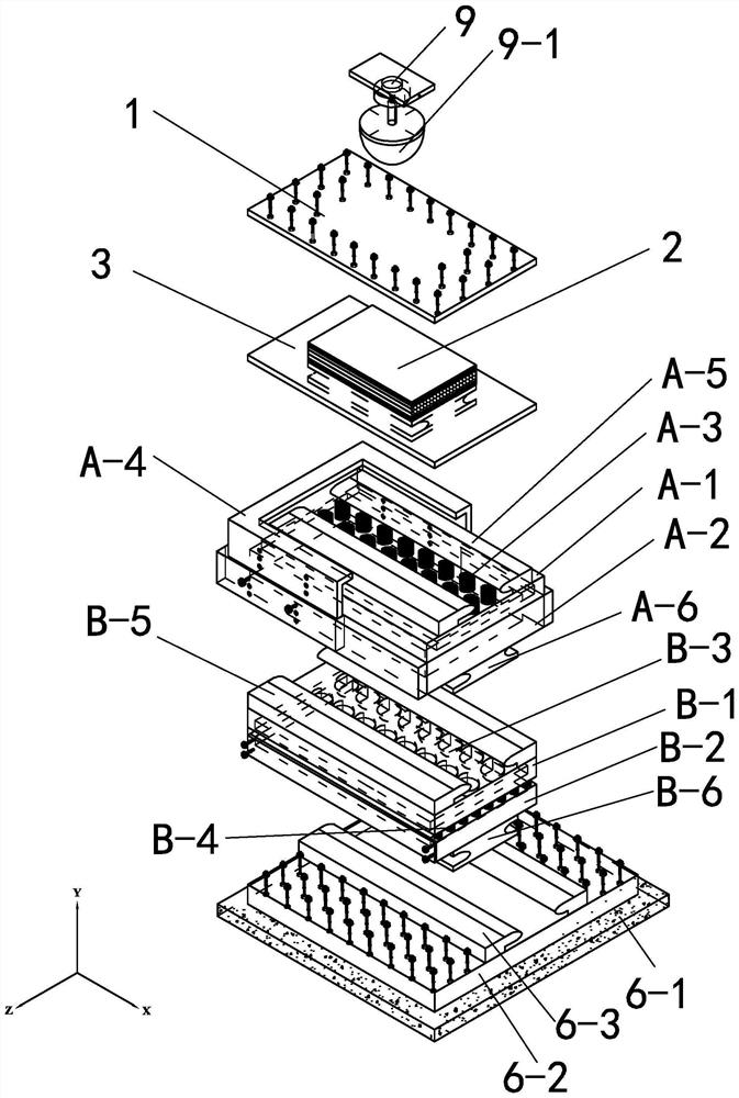
[0033] DETAILED DESCRIPTION One: Combination Figures 1 to 7 In the present embodiment, the impact test apparatus according to the present embodiment includes a spatial motion clipboard structure includes a splint 1, a lower mounting pinch 3, a vertical planar vibration device A, a horizontal planar motion device B, an experimental base 6, a signal The occurrence device 7 and the signal receiving apparatus 8, the signal generating device 7, and the signal receiving device 8 are opposed to the experimental base 6, and the horizontal planar motion device B is inserted on the experimental base 6, and the horizontal plane motion device B is located Between the signal generating device 7 and the signal receiving device 8, the vertical planar vibration device A is inserted on the horizontal planar motion device B, and the upper mounting splint 1 and the lower mounting splint 3 are buckled and the composite clamp plate 2 is sandwiched and the mounting splint 3 is mounted 3. The impact sig...

specific Embodiment approach 2

[0041] DETAILED DESCRIPTION 2: Combination Figure 1 to 3 In this embodiment, the lower mounting pinch 3 of the present embodiment includes a lower pinch plate 3-1 and a clamp slide 3-2, and the clamp slide 3-2 is fixedly mounted on the lower end surface of the lower pinch plate 3-1. As such, it is convenient to cooperate with the vertical plane vibration device A and slide. Other components and connection relationships are the same as those of the specific embodiments.

specific Embodiment approach 3

[0042] Detailed Embodiment 3: Combination Figure 1 to 3 In the present embodiment, the vertical planar vibration device A of the present embodiment includes an upper connection cover plate A-1, a lower connection cover plate A-2, a limiter A-4, and a plurality of vibration springs A-3, and a lower connection cover plate. The groove is opened in the A-2, and the plurality of vibrating springs A-3 are mounted inside the cover plate A-2, and the upper attached cover plate A-1 is attached to the plurality of vibrating springs A-3, and the cover plate A- 1 and the lower connection cover plate A-2 are connected by the limiter A-4, and the upper connection cover plate A-1 is located within the limiter A-4 and can be floated up and down under the action of the vibrating spring A-3. This is set, which is convenient for vibration in the vertical direction. Other components and connection relationships are the same as those of the specific embodiments.

[0043] The setting of the limiter of ...


PUM


Abstract

An impact testing device and an experimental method based on a space-moving sandwich plate structure, relating to an impact testing device and an experimental method. The invention solves the problem that the impact test of the existing fixing device cannot be used for the test simulation of the impact response behavior of the composite sandwich plate structure in a moving state. The horizontal plane moving device of the present invention is plugged on the experimental base, the vertical plane vibrating device is plugged on the horizontal plane moving device, the upper mounting splint and the lower mounting splint are buckled and the composite sandwich plate is clamped and installed on the vertical plane vibrating device . In the present invention, the impact signal excitation device guides the falling movement of the hammer head; the signal generating device and the signal receiving device measure the height and falling speed information corresponding to different positions of the impact hammer head at the time of falling. The invention is used for testing mechanical properties.

Description

Technical field [0001] The present invention relates to an impact test apparatus and an experimental method, and more particularly to an impact test apparatus and an experimental method based on a spatial motion clipboard structure. Background technique [0002] Composite sandwich board, or a sandwich clamping plate is a typical interlayer suction structure, which has a key role such as damage to the protection target to collision, impact, and improve the protection of the structure. The composite sandwich plate is mainly made of a panel prepared by a metal material or a non-metallic material, and a resistance material between the panels. Typically, the impact test for the composite clamp board is completed on the fixed device, i.e., mounted the test structure on a fixed experimental device, and then performs the corresponding impact test by impacting the device. [0003] In many engineering applications, a composite sandwich board as an important protection approach is often acc...

Claims


Application Information

Patent Timeline
Patent Type & Authority Patents(China)
IPC IPC(8): G01N3/303G01N3/02G01N3/06G01M7/08
CPCG01M7/08G01N3/02G01N3/06G01N3/068G01N3/303G01N2203/001G01N2203/0039G01N2203/0635G01N2203/0641G01N2203/0676G01N2203/0682
Inventor 路胜卓吴限德马加路陈卫东马敬鑫高天森吴世博陈光
Owner HARBIN ENG UNIV
Learn More