FPGA-based amplitude comparison angle measurement system and method

A technology of angle measurement and angle measurement by amplitude ratio, which is applied in the field of angle measurement system based on FPGA, which can solve the problems of increased delay of target arrival angle, time-consuming and laborious, loss of target data, etc., and achieve low delay and convenient management , the effect of reducing configuration requirements

Pending Publication Date: 2020-10-09
西安思丹德信息技术有限公司
View PDF5 Cites 0 Cited by
  • Summary
  • Abstract
  • Description
  • Claims
  • Application Information

AI Technical Summary

Problems solved by technology

[0003] At present, in engineering implementation, most of the DSP platform is used to realize the angle measurement algorithm; however, due to the large number of channels, the amount of data collected is relatively large, and the processing capacity of DSP is limited, so when using DSP to calculate the angle measurement algorithm, the target Feasible when the number is small, if there are many targets appearing at the same time, the delay in calculating the target angle of arrival will increase, and even part of the target data will be lost
In addition, due to the multi-beam array antenna system in different working environments and geographical locations, the receiving gain and amplitude characteristics of each channel will change, so it is necessary to perform real-time corrections at the actual working place, and repeatedly test and adjust various parameters. It is time-consuming and labor-intensive; therefore, using the DSP platform to perform angle measurement calculations in this system cannot meet the requirements of the system

Method used


Image

  • FPGA-based amplitude comparison angle measurement system and method
  • FPGA-based amplitude comparison angle measurement system and method
  • FPGA-based amplitude comparison angle measurement system and method

Examples


Embodiment Construction

[0039] The present invention will be further described in detail below in conjunction with specific embodiments, which are explanations of the present invention rather than limitations.

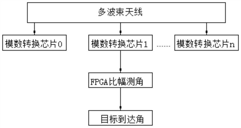
[0040] Such as figure 2 As shown, the present invention discloses a system for measuring angle ratios based on FPGA, including a multi-beam antenna, an analog-to-digital conversion chip and an FPGA chip, and a memory ROM is built in the FPGA chip; each channel of the multi-beam antenna is connected to a Analog-to-digital conversion chip, the analog-to-digital conversion chip is connected to the FPGA chip, the analog-to-digital conversion chip is used to convert the collected analog signal into a digital signal, and the FPGA chip is used to calculate the target angle of arrival, the target angle of arrival is the deviation angle, axial angle and the sum of the compensation angles.

[0041] After the analog signal collected by the antenna of each channel is converted into a digital signal by ...


PUM


Abstract

The invention discloses an FPGA-based amplitude comparison angle measurement system, which comprises a multi-beam antenna, an analog-to-digital conversion chip and an FPGA chip, and is characterized in that a memory ROM is arranged in the FPGA chip; each channel of the multi-beam antenna is connected with the analog-to-digital conversion chip, and the analog-to-digital conversion chips are connected with the FPGA chip. The invention further discloses an implementation method of the system. An analog signal acquired by the antenna of each channel is converted into a digital signal through AD conversion and then transmitted to the FPGA; and the FPGA firstly calculates the amplitude of the signal in each channel, then finds out the amplitude values of three adjacent channels with the maximumamplitude, calls the channel parameters in the memory based on the channel number of the channel with the maximum amplitude, calls a natural logarithm value of the reading amplitude according to an angle measurement mode, and calculates a target arrival angle according to a response formula. The FPGA chip is low in time delay and high in parallel processing speed, the ROM is used for storing parameter files needing to be modified, angle measurement values can be conveniently corrected in different geographical position occasions, debugging efficiency is improved, and later maintenance of a program is easy.

Description

technical field [0001] The invention belongs to the technical field of amplitude angle measurement, in particular to an FPGA-based amplitude angle measurement system and method. Background technique [0002] At present, the angle ratio measurement technology is used in the multi-beam array antenna system. The array antenna is an antenna system composed of many identical single antennas arranged according to certain rules. One or three narrow beams received signal amplitude, according to a certain calculation method to calculate the target angle of arrival technology. [0003] At present, in engineering implementation, most of the DSP platform is used to realize the angle measurement algorithm; however, due to the large number of channels, the amount of data collected is relatively large, and the processing capacity of DSP is limited, so when using DSP to calculate the angle measurement algorithm, the target It is feasible when the number is small. If there are many targets ...

Claims


Application Information

Patent Timeline
Patent Type & Authority Applications(China)
IPC IPC(8): G01S3/12G01S3/28
CPCG01S3/12G01S3/28
Inventor 张天明王晨付雷
Owner 西安思丹德信息技术有限公司
Why Eureka
Try Eureka