
Fixing device

A technology of holder and width, which is applied in the direction of instruments, electrical recording process equipment using charge patterns, optics, etc., can solve problems such as uneven clamping pressure distribution, and achieve suppression of clamping pressure distribution from becoming uneven, position The effect of stable precision

Pending Publication Date: 2020-10-09
BROTHER KOGYO KK
View PDF2 Cites 0 Cited by
  • Summary
  • Abstract
  • Description
  • Claims
  • Application Information

AI Technical Summary

Problems solved by technology

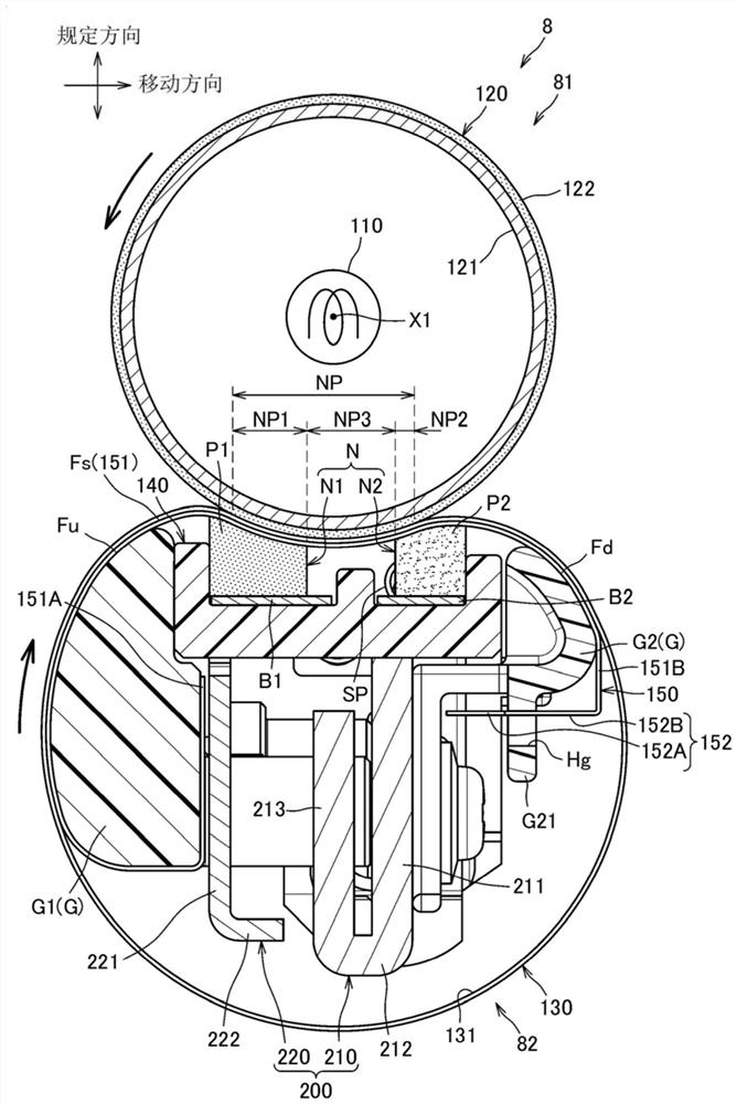
[0010] Here, the positional relationship between the holder and the stay has been determined based on the side guide. Therefore, due to the manufacturing error of the side guide or the assembly error of the stay and the holder relative to the side guide, the positional relationship from the stay to the holder The position where the workpiece input load (especially the position in the moving direction of the endless belt in the clamping part) will change, and the clamping pressure distribution may become uneven

Method used


Image

  • Fixing device
  • Fixing device
  • Fixing device

Examples


Embodiment Construction

[0102] Hereinafter, one embodiment of the invention will be described in detail with appropriate reference to the drawings.

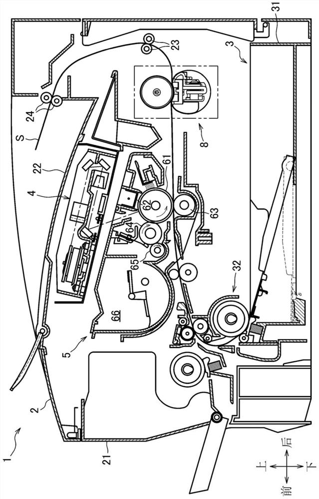
[0103] like figure 1 As shown, the fixing device 8 according to the embodiment is used in an image forming apparatus 1 such as a laser printer. The image forming apparatus 1 includes a main body housing 2 , a sheet supply unit 3 , an exposure device 4 , a developer image forming unit 5 , and a fixing device 8 .

[0104] The sheet supply unit 3 is provided at a lower portion inside the main body housing 2 , and includes a sheet tray 31 for storing sheets S such as paper, and a sheet supply mechanism 32 . The sheet S in the sheet tray 31 is supplied to the developer image forming unit 5 by the sheet supply mechanism 32 .

[0105] The exposure device 4 is disposed on the upper portion inside the main body casing 2, and includes a light source device not shown, a polygon mirror shown without reference numerals, a lens, a reflection mirror, and the like. ...


PUM


Abstract

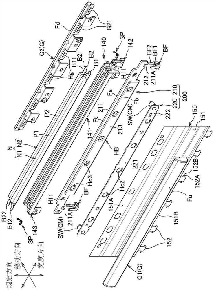
The invention provides a fixing device which stabilizes the positional accuracy of a holder with respect to the moving direction of a stay to which a load is input and suppresses unevenness of nip pressure distribution. The device comprises: a heater; a rotating body heated by the heater; an endless belt; a nip forming member that forms a nip by sandwiching the endless belt between the nip formingmember and the rotating body; a holder extending in a width direction of the endless belt and holding the nip forming member; a first stay extending in the width direction and supporting the holder;and a biasing member that biases the first stay toward the rotating body, the holder having: a holder main body that holds the nip forming member and is supported by the first stay; and an engaging portion that engages with an end portion of the first stay in the width direction, is disposed at a position different from the endless belt in the width direction, and protrudes from the end portion ofthe holder main body in the width direction, the engaging portion having: a pair of clamping walls that clamp the first stay in the moving direction of the endless belt in the clamping portion; and afirst connecting wall connecting the pair of clamping walls.

Description

technical field [0001] The present invention relates to a fixing device having an endless belt. Background technique [0002] Conventionally, as a belt-type fixing device, there is known a fixing device that includes: a pad that sandwiches an endless belt with a heating roller; a holder that holds the pad; a stay, The stay supports a holder; and a side guide that holds the holder and an end in the width direction of an endless belt of the stay (refer to Patent Document 1). In addition, in this technique, the contact surface between the holder and the stay is a flat surface that extends from one end side of the holder to the other end side and is long in the width direction of the endless belt. [0003] Also, as a belt-type fixing device, for the purpose of suppressing wrinkles on recording media such as envelopes, it has been proposed to dispose both upstream pads and downstream pads with a gap therebetween (see Patent Document 2). Specifically, this technique includes an ...

Claims


Application Information

Patent Timeline
Patent Type & Authority Applications(China)
IPC IPC(8): G03G15/20G03G21/16
CPCG03G15/2053G03G21/1685G03G2215/2009G03G15/206G03G15/2028G03G15/757
Inventor 渡边知范半田浩司福江修平竹内健二田口和奈小笠原达夫
Owner BROTHER KOGYO KK
Learn More